AG-tronik M1 AND REGULATOR PR-9
INSTRUCTIONS FOR USE – rev. 2017-04
7
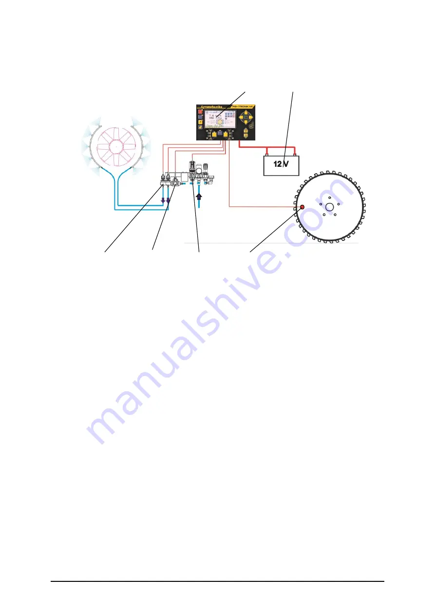
3. FUNCTION DIAGRAM OF THE SYSTEM
1
6
2
4
5
3
Figure 6
1.
AG-tronik M1
2.
Distributing solenoid valves
3.
Speed sensor
4.
Flow sensor
5.
Pressure regulator
6.
Power supply 12 V
AG-tronik receives information, required for calculation of actual liter per hectare from:
flow sensor, which is built in regulator PR 9EC and
speed sensor, which is fitted on the front tractor wheel for carried sprayers or
sprayer wheel for driven sprayers.
Flow sensor is a component part of regulator PR 9EC and is connected to electric connection
cabinet on the flow regulator.
Speed sensor can be connected in two manners:
for driven sprayers on connector of cable harness of the regulator PR-9 EC,
for carried sprayers, in the housing of AG-tronik (4-pole connector, fig. 2).
AG-tronik is supplied through three-pole connector (figure 3) on tractor electrical circuit
with 12 V voltage.
AG-tronik regulates work pressure through regulation valve on the regulator, depending on
flow capacity. It ensures that flow capacity equals desired flow capacity (hectare
consumption).


