background image

WARNING: To reduce the risk of injury, user 

must read instruction manual.


Symbols used in this manual


V……..volts 
A……..amperes 
Hz……hertz 
W……..watt


~………alternating current 

n

0

………no load speed


/min……..revolutions or reciprocation per 
minute


  ………….class II tool


SPECIFIC SAFETY RULES


1.


Never operate 

the tool in an area with


flammable  solids,  liquids,  or  gases. 
Sparks  from  the  commutator/carbon 
brushes could cause a fire or explosion. 


Warning

:

Risk of injury from high-

temperature chips!  
High-temperature chips are expelled 

at high speed.  


Never touch the tool holder and keep 
all vulnerable body parts clear while 
the machine is running. 


2.


Always  guide  the  machine  away  from 
the body while working.  

3.


Do  not  work  holding  the  machine 

above your head.  


WARNING! Some dust created by 

power grinding contains chemicals 

known to cause cancer, birth defects  

or other reproductive harm.


An example of these chemicals are: 

lead from lead-based paint


Your  risk  from  these  exposures  varies, 
depending  on  how  often  you  do  this 
type of work. To reduce your exposure 
to  these  chemicals:  work  in  a  well 
ventilated  area,  and  work  with 
approved  safety  equipment,  such  as 
those  dust  masks  that  are  specifically 
designed  to  filter  out  microscopic 
particles.


WARNING!: Never machine materials


which contain asbestos.


4.


Use only recommended 

carbide


i n s e r t s , r a t e d a t t h e m a c h i n e ’ s


maximum rated cutting rate or higher.


5.


Do  not  use  dull  or  damaged 

carbide


inserts.  Dull  inserts  cause  excessive 
friction  and  binding  and  excessive 
load on the motor, leading to possible 
damage. 


6.


Important: 

After 

completing 

the 

operation, 

Wait for coasting tool holder


to  stop  rotating  completely  before 
putting the machine down. 


7.


Maintain labels and nameplates. 

These


c a r r y i m p o r t a n t i n f o r m a t i o 
n  .  I  f  unreadable  or  missing,  obtain  a 
replacement.


FUNCTIONAL DESCRIPTION INTENDED USE


This shape beveling and deburring tool is an 

electrically driven portable machine:


7


Содержание 1100W Electric Beveler model B16

Страница 1: ...ction manual 1800W Electric Beveler model B15 1100W Electric Beveler model B16 AC Induction Motor Mode For your personal safety READ and UNDERSTAND before using SAVE THESE INSTRUCTIONS FOR FUTURE REFERENCE 2 ...

Страница 2: ...30 mm Net Weight 6 5kgs 14 3Lbs Variable speed wheel Auxiliary handle Bevel height scale Adjustable dial ring Support deck Indexable Main handle On off trigger switch with lock pin Tool holder Impeller carbide insert Warning Tools equipped with over load protection when motor has been cut off due to over load always switch on machine with no load for at least 20 seconds to reduce temperature befor...

Страница 3: ...3000 60 Deg 12 7mm 45 Deg 16mm MAX adjustment for steel up to 45kg mm2 37 5 Deg 15 6mm 30Deg 14mm 15 Deg 12mm Net weight 19 3 kgs 42 46 Lbs Handle On Off Switch Side Handle Depth adjust nut AC induction motor Depth Angular Adjustment Screw Adjustment Screw Impeller Front Handle Angular adjustment form 15 60 Deg 4 12 carbide insert tool holder ...

Страница 4: ...s are equipped with a polarized plug one blade is wider than the other This plug will fit in a polarized outlet only one way If the plug does not fit fully in the outlet reverse the plug If it still does not fit contact a qualified electrician to install a polarized outlet Do not change the plug in any way Double insulation 1100W Electric Beveler Mode 1800W Electric Beveler Mode only eliminates th...

Страница 5: ...l if switch does not turn it on or off Any tool that cannot be controlled with the switch is dangerous and must be repaired Disconnect the plug from the power source before making any adjustments changing accessories or storing the tool Such preventive safety measures reduce the risk of starting the tool accidentally Store idle tools out of reach of children and do not allow persons unfamiliar wit...

Страница 6: ...ese chemicals are lead from lead based paint Your risk from these exposures varies depending on how often you do this type of work To reduce your exposure to these chemicals work in a well ventilated area and work with approved safety equipment such as those dust masks that are specifically designed to filter out microscopic particles WARNING Never machine materials which contain asbestos 4 Use on...

Страница 7: ... is damaged A damaged cable must be replaced immediately by an authorized Customer Service Center Do not try to repair the damaged cable yourself The use of damaged power cables can lead to an electric shock Extension cable If an extension cable is required it must have a sufficient cross section so as to prevent an excessive drop in voltage or overheating An excessive drop in voltage reduces the ...

Страница 8: ...teel ruler or other accurate device with a right angle While keeping the ruler square with the impeller and the support deck slowly adjust the support deck until the ruler just touches the carbide insert This is the zero point 3 Once the zero point is found loosen the small set screw and turn the dial ring to indicate zero on the scale Then retighten the set screw Carbide insert Impeller Ruler Sup...

Страница 9: ...rder to achieve better beveling result 1 Using the supplied L type torx wrench Loosen fixing screw and remove the carbide insert 2 Index the carbide insert to the next sharp edge or insert a new one as needed 3 Retighten carbide insert with its torx fixing screw Tool holder Carbide insert L type torx wrench REMOVING THE TOOL HOLDER DISCONNECT TOOL FROM POWER SOURCE WARNING Danger of Burns Tool hol...

Страница 10: ...er and loosen the tool holder from spindle 4 Rotate remove or replace the tool holders as needed 5 Using the supplied M3 Hex wrench loosen fixing screw and remove the carbide inserts 6 Rearrange the carbide insert to the other sharp edge or insert a new one as needed 7 Fasten carbide inserts glue up the fixing screws a suitable adhesive such as Loctite 8 A s s e m b l y i s t h e r e v e r s e o f...

Страница 11: ...ll rotate for a time Take care that parts of your body do not come into contact with the rotating parts or set the machine down while it is still rotating For 1100W Electric Beveler AC Induction Motor Mode Note For your own safety Always wear goggle and take precautions before operating the beveler Make sure fully understanding and compliance to the safety rules before use 1 Press green motor on b...

Страница 12: ...ctive the spindle is spinning clockwise so always operate in the direction from left to right up mill When performing inside bevels work in a clockwise direction only Do not bevel more than about 2mm per pass If more depth is needed make multiple passes until the desired bevel height is reached MAINTENANCE 1 Keep tool clean Periodically blow out all air passages with dry compressed air All plastic...

Страница 13: ...ace First unplug the machine Carefully remove the 4 screws to separate the rear handle halves and then remove the 4 screws which connect the handle to the motor housing Lift away the left hand handle half first There will still be wires connected to the rear handle so take care that these are not stressed Simply hold the rear handle off to one side Using pliers rotate the brush spring out of the w...

Страница 14: ...when it is retightened If the replacement of the power supply cord is necessary this has to be done by the manufacturer or their agent in order to avoid a safety hazard 15 ...

Страница 15: ...WIRING 1800W Mode 17 ...

Страница 16: ...WIRING 1100W AC Induction Motor Mode MOTOR 3 WAY CONNECTOR SWITCH BLACK RED YELLOW BLACK EARTH AC CAPACITOR ...

Страница 17: ......

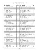
Страница 18: ...x 10 1 49 INDEXABLE CARBIDE INSERT 5 17 FLAT WASHER ø4 x ø10 x 1 1 50A TOOL HOLDER 45 45 1 18 PLASTIC WASHER ø4 x ø11 x 1 1 50B TOOL HOLDER 30 Optional 30 1 19 PICKUP MAGNET ø8 x ø15 x 5 1 50C TOOL HOLDER 37 5 Optional 37 5 1 20 SPACER ø8 x ø12 x 10 5 1 51 SPACER ø8 1 x ø14 x 5 5 1 21 MOTOR HOUSING 1 52 INTERNAL CIRCLIP R 22 1 22 STATOR 1 53A IMPELLER 45 45 ø27 x 14 5 1 23 SCREW M5 x 60 2 53B IMPE...

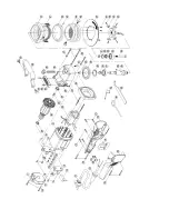
Страница 19: ...Induction Motor Mode 37 36 35 34 17 33 21 20 19 18 14 13 11 10 09 12 11 10 09 08 07 38 39 40 23 41 24 22 06 05 04 03 15 16 17 61 32 31 30 29 42 43 28 27 26 44 25 45 47 48 46 49 50 51 52 53 55 54 50 56 57 02 50 01 58 59 60 24 ...

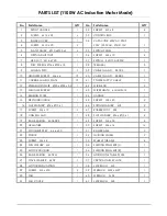
Страница 20: ... 5 1 42 WIRE LEAD 2 13 MILLING RECEIVER 1 43 WIRE SHEATH 6mmx15cm 1 14 BEARING PLATE 1 44 HANDLE 1 15 DEPTH INDICATOR 1 45 SCREW M8 x 40 2 16 FLAT WASHER Ø4 x Ø10 x 1 1 46 SPRING WASHER M8 2 17 SCREW M4 x 10 5 47 RUBBER FOOT 30L 4 18 CABLE GLAND 1 48 FLAT WASHER Ø6 x Ø13 x 1 4 19 BALL BEARING 6004 2RS 1 49 SCREW M6 x 30 4 20 ARMATURE 1 50 SCREW M6 x 16 16 21 WOODRUFF KEY 6 x 6 x 30 1 51 ROLLER AXL...

Страница 21: ...N KO spol s r o Táborská 398 22 293 01 Mladá Boleslav Czech republic phone 420 326 772 001 fax 420 326 774 279 e mail nko nko cz ...

Страница 22: ......

Страница 23: ......

Страница 24: ......

Отзывы: