


Agilent U5309A PCIe High-Speed Digitizer Introduction
Agilent U5309A PCIe High-Speed Digitizer Introduction
The scope of this Startup Guide is to detail the processes of receiving and installing the Agilent U5309A PCIe
High-Speed Digitizer, installing the required software, and verifying basic module operation. If you have any
questions after reviewing this information, please contact your local Agilent representative or contact us through
our website at
www.agilent.com/find/contactus
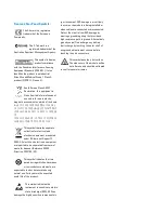
Related Documentation
This Startup Guide and the documentation listed below are contained on the
CD supplied with your product and at
Select
Technical Support > Manuals
.
l
U5309A User Manual
l
Help systems for the Agilent device drivers (IVI-C and IVI-COM, and
LabVIEW G)
l
Product specifications (Data Sheet)
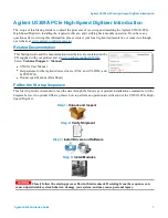
Follow the Startup Sequence
This Start-Up Guide is intended to lead the user through the four steps of product installation as summarized in the
diagram below. An optional fifth step shows how to perform an operational verification of the U5309A PCIe High-
Speed Digitizer.
Step 1
: Unpack and Inspect
Step 2
: Verify Shipment
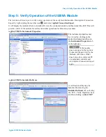
Step 3
: Install Drivers and Software
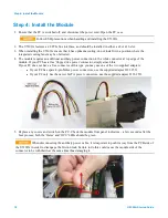
Step 4
: Install Modules
Closely follow the startup process flow in this document. Deviating from the sequence can
cause unpredictable system behavior, damage your system, and may cause personal injury.
Agilent U5309A Startup Guide
7
Содержание U5309A
Страница 6: ...Documentation Map Documentation Map 6 U5309A Startup Guide...
Страница 8: ...8 U5309A Startup Guide...
Страница 19: ...19 U5309A Startup Guide...