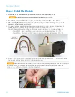
Step 4: Install the Module
Agilent U5309A Front Panel Features
Front Panel Connectors
Connector
Type
Description
TRG IN
MMCX
An external trigger signal input,
50 Ω terminated.
Level range is ±5 V.
IN 1 to IN 2
1
1 to 8
2
SSMC
Analog signal input.
A DC-coupled, 50 Ω terminated.
Maximum input voltage ±3.4 V DC.
JTAG
Micro
USB
Provides connection to the DPU for use with
the U5340A FPGA Development Kit.
TRG OUT
MMCX
Trigger Out signal.
User selectable from several functions.
I/O 1, 2, 3
MMCX
User configurable Input / Output signal.
3.3 V CMOS and TTL compatible.
CLK IN
MMCX
External clock input.
AC coupled and 50 Ω terminated,
signal level: +5 to +15 dBm.
Please refer to datasheet for details.
REF IN
MMCX
External reference clock input,
AC coupled and 50 Ω terminated.
It can accept a 100 MHz signal from
-3 to +3 dBm.
Note: It is recommended to first connect the SSMC end of the input cable
and tighten using the torque wrench (U1092-WCK) before connecting the
SMA end, this minimizes strain on the connector. A 1 m SSMC to SMA
cable is available as an accessory (U1092-CB3).
1
For the 2 channels version (U5309A-CH2 option)
2
For the 8 channels version (U5309A-CH8 option)
Agilent U5309A Startup Guide
15
Содержание U5309A
Страница 6: ...Documentation Map Documentation Map 6 U5309A Startup Guide...
Страница 8: ...8 U5309A Startup Guide...
Страница 19: ...19 U5309A Startup Guide...


