


associated with local AC mains connections.
Assume all measurement, control, and data
I/O connections are for connection to
Category I sources unless otherwise marked
or described in the user documentation.
Exercise extreme caution when a shock
hazard is present. Lethal voltage may be
present on cable connector jacks or test
fixtures. The American National Standards
Institute (ANSI) states that a shock hazard
exists when voltage levels greater than 30V
RMS, 42.4V peak, or 60VDC are present. A
good safety practice is to expect that
hazardous voltage is present in any unknown
circuit before measuring.
Operators of this product must be protected
from electric shock at all times. The
responsible body must ensure that operators
are prevented access and/or insulated from
every connection point. In some cases,
connections must be exposed to potential
human contact. Product operators in these
circumstances must be trained to protect
themselves from the risk of electric shock. If
the circuit is capable of operating at or
above 1000V, no conductive part of the
circuit may be exposed.
Do not connect switching cards directly to
unlimited power circuits. They are intended
to be used with impedance-limited sources.
NEVER connect switching cards directly to
AC mains. When connecting sources to
switching cards, install protective devices to
limit fault current and voltage to the card.
Before operating an instrument, ensure that
the line cord is connected to a properly-
grounded power receptacle. Inspect the
connecting cables, test leads, and jumpers
for possible wear, cracks, or breaks before
each use.
When installing equipment where access to
the main power cord is restricted, such as
rack mounting, a separate main input power
disconnect device must be provided in close
proximity to the equipment and within easy
reach of the operator.
For maximum safety, do not touch the
product, test cables, or any other
instruments while power is applied to the
circuit under test. ALWAYS remove power
from the entire test system and discharge
any capacitors before: connecting or discon-
necting cables or jumpers, installing or
removing switching cards, or making internal
changes, such as installing or removing
jumpers.
Do not touch any object that could provide a
current path to the common side of the
circuit under test or power line (earth)
ground. Always make measurements with dry
hands while standing on a dry, insulated
surface capable of withstanding the voltage
being measured.
The instrument and accessories must be
used in accordance with its specifications
and operating instructions, or the safety of
the equipment may be impaired.
Do not exceed the maximum signal levels of
the instruments and accessories, as defined
in the specifications and operating
information, and as shown on the instrument
or test fixture panels, or switching card.
When fuses are used in a product, replace
with the same type and rating for continued
protection against fire hazard.
Chassis connections must only be used as
shield connections for measuring circuits,
NOT as safety earth ground connections.
If you are using a test fixture, keep the lid
closed while power is applied to the device
under test. Safe operation requires the use
of a lid interlock.
Caution and Warning Notices
A CAUTION notice denotes a hazard. It calls
attention to an operating procedure,
practice, or the like that, if not correctly
performed or adhered to, could result in
damage to the product or loss of important
data. Do not proceed beyond a CAUTION
notice until the indicated conditions are fully
understood and met.
A WARNING notice denotes a hazard. It
calls attention to an operating procedure,
practice, or the like that, if not correctly
performed or adhered to, could result in
personal injury or death. Do not proceed
beyond a WARNING notice until the
indicated conditions are fully understood
and met.
Instrumentation and accessories shall not be
connected to humans.
Before performing any maintenance,
disconnect the line cord and all test cables.
To maintain protection from electric shock
and fire, replacement components in mains
circuits – including the power transformer,
test leads, and input jacks – must be
purchased from Agilent. Standard fuses with
applicable national safety approvals may be
used if the rating and type are the same.
Other components that are not safety-
related may be purchased from other
suppliers as long as they are equivalent to
the original component (note that selected
parts should be purchased only through
Agilent to maintain accuracy and
functionality of the product). If you are
unsure about the applicability of a
replacement component, call an Agilent
office for information.
Cleaning Precautions:
To prevent electrical shock, disconnect the
Agilent Technologies instrument from mains
before cleaning. Use a dry cloth or one
slightly dampened with water to clean the
external case parts. Do not attempt to clean
internally. To clean the connectors, use
alcohol in a well-ventilated area. Allow all
residual alcohol moisture to evaporate, and
the fumes to dissipate prior to energizing the
instrument.
Содержание U5309A
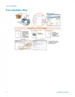
Страница 6: ...Documentation Map Documentation Map 6 U5309A Startup Guide...
Страница 8: ...8 U5309A Startup Guide...
Страница 19: ...19 U5309A Startup Guide...