


Installation Note
E4440-90632
27
Installation Procedure
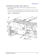
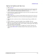
Replace the Top Brace and Outer Case
1. Refer to
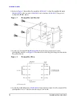
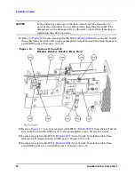
2. Carefully position the top brace on the deck. The alignment pin at the center of the
web/fan assembly must mate with the alignment hole on the top brace. Make sure
that no coaxial cables will get pinched underneath the brace.
3. Use the T-10 driver to replace and tighten the top screws first; then replace the side
screws. Torque to 101 Ncm (9 in-lb).
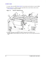
4. Refer to
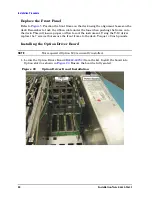
5. Slide the instrument cover back onto the deck from the rear. The seam on the cover
should be on the bottom. Be sure the cover seats into the gasket groove in the front
frame.
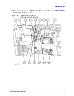
6. Replace the four rear feet onto the rear of the instrument. Torque to 236 Ncm (21
in-lb).
7. Use the T-20 driver to replace the handles. Torque to 236 Ncm (21 in-lb).
8. Replace the four bottom feet by pressing them into the holes in the case and sliding
them in the opposite direction of the arrows until they click into place. Note that the
feet at the front have the tilt stands.
9. Remove the existing warning label near the RF input connector. Attach the new
warning label (
) included in this kit to the same location on the front
panel.


