


10
Installation Note
E4440-90632
Installation Procedure
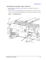
CAUTION
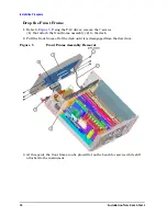
In the following step, use a 7/16-inch wrench on one of the wrench flats
at the ends of the filter to prevent the filter body from rotating when
removing the cable. Cables can be damaged if the low pass filter is
allowed to rotate when loosening or tightening the cable connector.
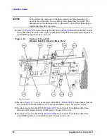
6. Locate and remove cable W48 (low pass filter and J1 on the preamplifier). Discard
this cable, since it will be replaced by another cable.
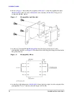
7. Uninstall the preamplifier and the ribbon cable. Use a T-10 Torx driver to remove the
two screws.
Figure 4
Remove the Preamplifier


