3-32
Service Guide E8364-90001
Tests and Adjustments
PNA Series Microwave Network Analyzers
Performance Tests (Agilent N2721A Software Package)
E8362A, E8363A, E8364A
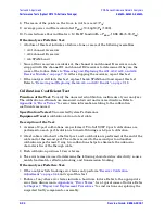
Trace Noise Test
Function of the Test:
To measure the stability of a signal in the internal source and
receiver system of your analyzer.
Specification Tested:
Test Port Input–Trace Noise Magnitude and Trace Noise Phase
Equipment Used:
A test cable.
Description of the Test:
1. Port 1 and Port 2 are connected with a test cable.
2. The analyzer is set to a series of CW frequencies across its frequency range.
3. Magnitude and phase are measured at each frequency at both 1 kHz and 10 kHz IF
bandwidths, in both directions.
4. All measurements are made at a nominal power level of 0 dBm and with 201 points per
sweep.
If the Analyzer Fails this Test:
• Repeat this test. It is unlikely for the analyzer to fail this test without a complete
failure of the network analyzer system.
• If the analyzer still fails this test, perform the
“Receiver Calibration Adjustment” on
and repeat this test.
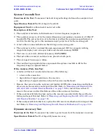
Receiver Compression Test
Function of the Test:
To measure the compression at the analyzer’s specified maximum
power level for the receivers.
Specification Tested:
Test Port Input–Maximum Test Port Input Level
Equipment Used:
The compression test set (Z5623A Option K01), a power meter, power
sensors, two test cables, and a calibration kit. (And 10-dB and 20-dB pads if the analyzer
does not have an internal step attenuator.)
Description of the Test:
1.
All measurements are made with a 50 kHz IF bandwidth and 201 points per sweep.
2.
The measurements are made separately on each port.
3.
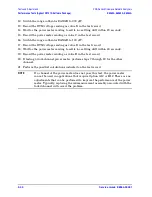
The analyzer is set to various CW frequencies across the range of the analyzer.
4.
A power sensor is connected to the “signal source point” to be used to test the port. The
“signal source point” may be either the port connector itself, when a short is used, or
the end of the test cable, when the compression test set is used.
5.
The analyzer source output level is adjusted to create the maximum power level
specified for the receiver.
6.
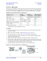
The power sensor is disconnected and the “signal source point” is connected to the port
to be tested.
7.
The absolute log magnitude value (dBm) for the reference channel on the source port is
read.
Содержание E8362A
Страница 11: ...Service Guide E8364 90001 1 1 1 Safety and Regulatory Information ...
Страница 19: ...Service Guide E8364 90001 2 1 2 General Product Information ...
Страница 29: ...Service Guide E8364 90001 3 1 3 Tests and Adjustments ...
Страница 79: ...Service Guide E8364 90001 4 1 4 Troubleshooting ...
Страница 139: ...Service Guide E8364 90001 5 1 5 Theory of Operation ...
Страница 169: ...Service Guide E8364 90001 6 1 6 Replaceable Parts ...
Страница 215: ...Service Guide E8364 90001 7 1 7 Repair and Replacement Procedures ...
Страница 287: ...Service Guide E8364 90001 A 1 A Error Terms ...
Страница 302: ...A 16 Service Guide E8364 90001 Error Terms PNA Series Microwave Network Analyzers Error Term Data E8362A E8363A E8364A ...
Страница 303: ...Service Guide E8364 90001 B 1 B Option Enable Utility ...
Страница 309: ...Service Guide E8364 90001 C 1 C Firmware Upgrades ...
Страница 313: ...Service Guide E8364 90001 D 1 D Operating System Recovery ...

