background image

 6                                                                                                                                  Installation Note E4411-90045

Removing the Front Frame

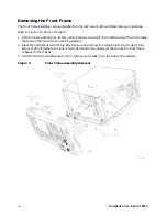
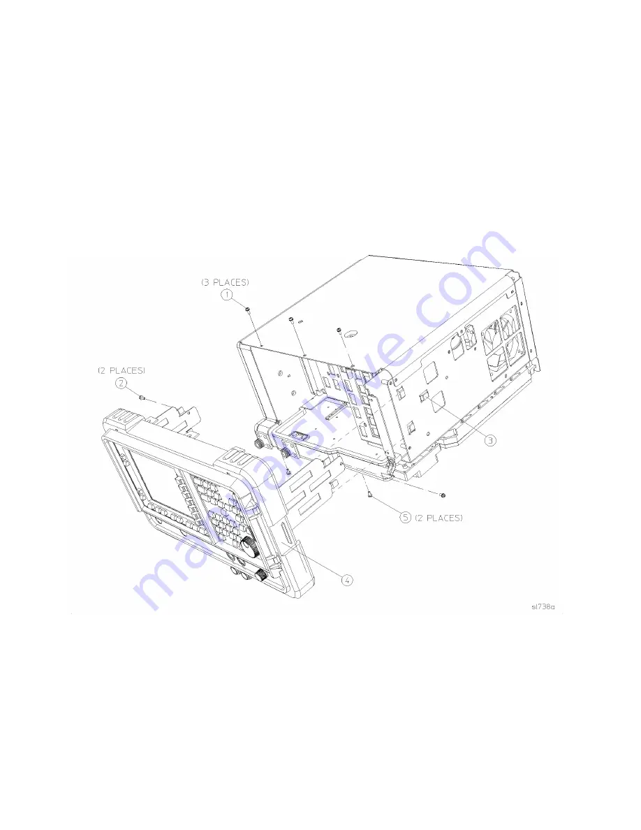
The front frame assembly can be extended from the instrument without detaching any connections.

Refer to

Figure 3

 for steps 1 through 3.

1. With the instrument still on its face, remove the two screws (5) on the bottom side of the instrument

that secure the front frame to the RF assembly.

2. Place the instrument with the top side facing up and remove the remaining three screws (1) that

secure the front frame to the inner shield. Remove the two screws (2) that secure the front frame
subpanel to the chassis.

3. Slide the front frame (4) forward until it catches on the tabs (3) on the sides of the chassis.

Figure 3

 Front Frame Assembly Removal

Содержание E4411-60019

Страница 1: ...Part Number E4411 90045 Supersedes October 1998 Printed in USA May 2000 Installation Note Agilent Technologies ESA Spectrum Analyzer Gasket Upgrade Kit Kit Number E4411 60019 ...

Страница 2: ...this material including but not limited to the implied warranties of merchantability and fitness for a particular purpose Agilent Technologies shall not be liable for errors contained herein or for incidental or consequential damages in connection with the furnishing performance or use of this material Copyright 1998 1999 2000 Agilent Technologies Inc ...

Страница 3: ... a lens keypad assembly Because of variations in these assemblies it has been left up to the person performing the upgrade to order the appropriate lens keypad assembly for the instrument Refer to the instrument service guide for the applicable part number Product Affected ESA Spectrum Analyzers Serial Numbers All Options All To Be Performed By X Agilent Technologies Service Center Personnel Quali...

Страница 4: ...ages Failure to heed the safety precautions can result in severe or fatal injury CAUTION Electrostatic discharge ESD can damage or destroy electronic components All work on electronic assemblies should be performed at a static safe workstation Refer to the documentation that pertains to your instrument for information about static safe workstations and ordering static safe accessories Description ...

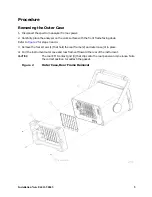
Страница 5: ...me facing down Refer to Figure 2 for steps 3 and 4 3 Remove the four screws 1 that hold the rear frame 2 and outer case 4 in place 4 Pull the instrument outer case and rear frame off toward the rear of the instrument CAUTION The rear EMI contact grid 3 that clips onto the rear panel can come loose Note the correct position to reattach the gasket Figure 2 Outer Case Rear Frame Removal ...

Страница 6: ... two screws 5 on the bottom side of the instrument that secure the front frame to the RF assembly 2 Place the instrument with the top side facing up and remove the remaining three screws 1 that secure the front frame to the inner shield Remove the two screws 2 that secure the front frame subpanel to the chassis 3 Slide the front frame 4 forward until it catches on the tabs 3 on the sides of the ch...

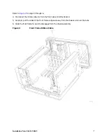
Страница 7: ... 6 4 Disconnect the ribbon cable 1 from the front panel interface board 5 Carefully pull the sides of the front frame subpanel away from the chassis and over the tabs 6 Slide the front frame forward to disengage from the chassis assembly Figure 4 Front Frame Ribbon Cable ...

Страница 8: ...is delicate With a small screwdriver or similar tool gently push the lock tabs out from the back of the connector Excessive force on the locking tab will brake the retaining clips and if broken board replacement will be necessary 3 Disconnect the W3 display ribbon cable 2 from the front panel interface board The ribbon cable connector has a lock that needs to be slid out before removing the ribbon...

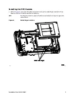
Страница 9: ...r to Figure 6 Use a pair of needle nose pliers to remove the metal fingers located in three places on the front frame around the lens opening NOTE The fingers are held in place with adhesive and some force may be required to remove them Figure 6 Metal Finger Location ...

Страница 10: ...asket to adhere it to the frame 4 Repeat steps 3a through 3c with the remaining short gasket along the opposite edge of the opening 5 Repeat steps 3a through 3c to install one of the long gaskets along the top or bottom edge of the opening as shown in the figure NOTE Make sure that the long gaskets touch the ends of the short gaskets This is necessary to create an airtight seal around the inner pl...

Страница 11: ...ad assembly for the repair Removing the Keypad Flex Circuit 1 Remove the volume knob and the RPG knob by pulling straight off of the control shafts NOTE There is a water seal gasket placed around the volume control shaft that will need to be repositioned during the replacement procedure Refer to Figure 8 for steps 2 and 3 2 Remove the six screws 1 securing the subpanel 2 to the front frame 5 Lift ...

Страница 12: ...control shaft is correctly positioned 5 Ensure that the flex circuit is aligned with the pegs and not visible through the screw holes in the subpanel Replace the six screws that secure the subpanel to the front frame Replace the four screws that secure the display to the front frame Torque to 101 N cm 9 inch pounds 6 Press the volume and RPG knobs onto their control shafts Reinstalling the Display...

Страница 13: ...ecure the front frame to the chassis Torque to 101 N cm 9 inch pounds Replacing Outer Case 1 Replace the instrument outer case by matching the grill on the side of the case to the fan on the power supply assembly 2 Fit the leading edge of the case completely into the slot on the back of the front frame assembly Refer to Figure 2 for steps 3 through 5 3 Replace the rear frame assembly 2 on the inst...

Страница 14: ...pair After the spectrum analyzer assemblies have been repaired or replaced perform the related adjustments and performance verification tests Refer to the Adjustment and Tests for Replacement or Repaired Assemblies in the Post Repair Procedures chapter of the service guide for the related adjustments and performance verification tests required for each assembly ...

Отзывы: