background image

Getting Started  

15

Modes of Operation

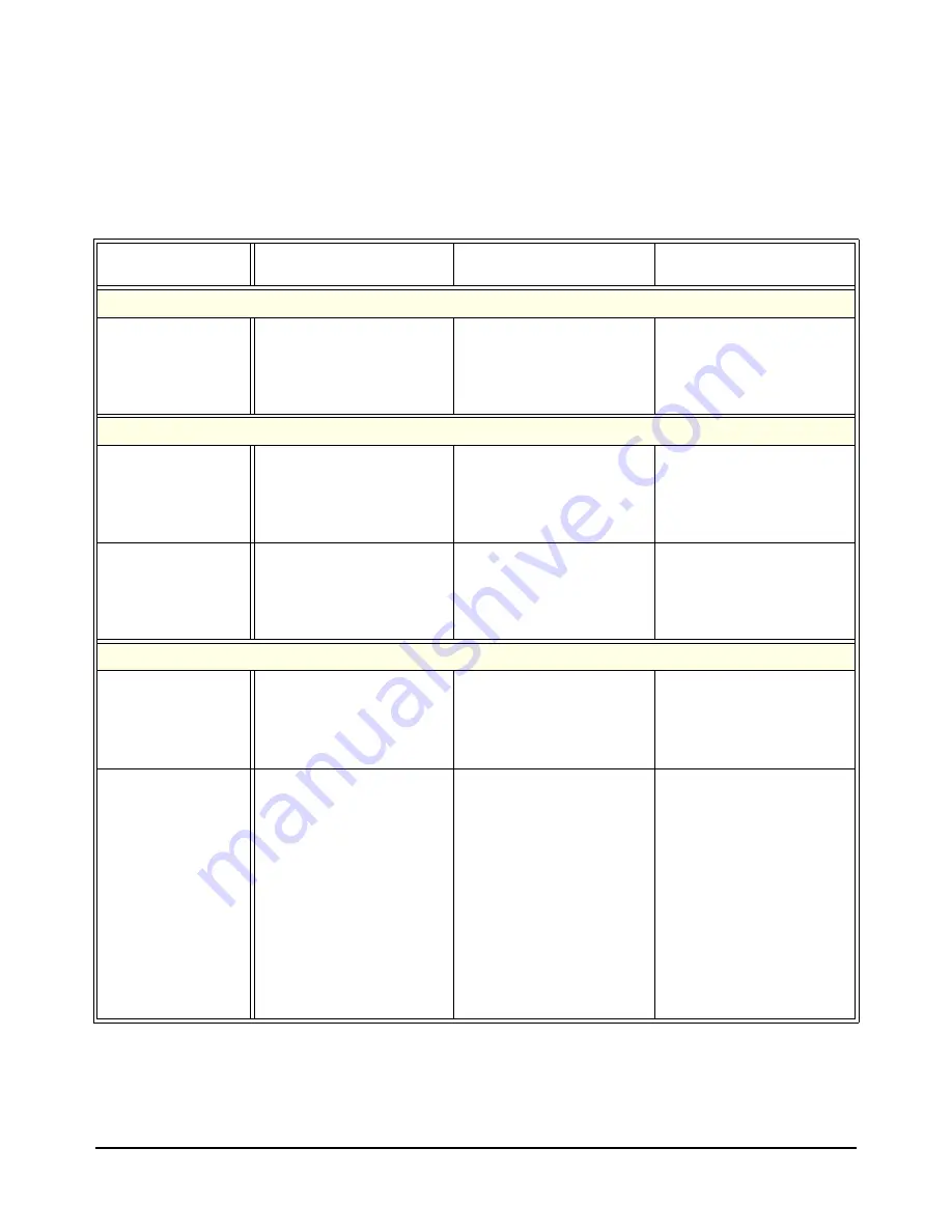
Table 1-1 summarizes the modes of operation for the Relay Driver Module. 
For 36-channel operation, note that CNFG 1 sets the actuation mode 
(simultaneous actuation or stepped actuation) for the channel pairs, while 
CNFG 2 sets the method of current output from the channel pairs 
(continuous output or pulsed output).

Table 1-1. Relay Driver Module Operating Modes

Operation

Switching One Channel

Switching 

Multiple Channels

Scanning 
Channels

72-Channel Mode  (Set when CNFG 0 is Open)

OPEN (@ccnn) opens 
the channel and CLOSe 
(@ccnn) closes the channel.

All channels in the 
OPEN/CLOSe 

channel_list


are actuated nearly 
simultaneously.

A  60-msec delay occurs 
between actuations of each 
channel in the SCAN 

channel_list

.

36-Channel Mode Actuation (Valid only when CNFG 0 is connected to GROUND)

Simultaneous 
Actuation
(CNFG 1 Open)

OPEN (@ccnn) opens 
the channel pair and CLOSe 
(@ccnn) closes the channel 
pair.

All channel pairs (SET/ 
RESET) in the OPEN/CLOSe 

channel_lis

t are actuated 

nearly simultaneously. 

A  60-msec delay occurs 
between actuations of each 
channel pair in the SCAN 

channel_list

.

Stepped Actuation
(CNFG 1 connected 
to GROUND)

OPEN (@ccnn) opens 
the channel pair and CLOSe 
(@ccnn) closes the channel 
pair.

A 30-msec delay occurs 
between actuations of each 
channel pair in the OPEN/ 
CLOSe 

channel_list

.

A  60-msec delay occurs 
between actuations of each 
channel pair in the SCAN 

channel_list

.

36-Channel Mode Current Output (Valid only when CNFG 0 is connected to GROUND)

Continuous Output 
(CNFG 2 Open)

The SET or RESET output 
current is continuously 
applied to the channel pair 
when actuated.

The SET or RESET output 
current is continuously 
applied to the channel pair 
that is actuated.

The SET or RESET output 
current is continuously 
applied to the channel pair 
that is actuated.

Pulsed Output
(CNFG 2 connected 
to GROUND)

When the channel pair is 
actuated, the SET or RESET 
output current is applied until 
the 30 msec timer indicates 
the channel has finished 
moving. The current is then 
removed, and another 30 
msec wait occurs. 

The SET or RESET output 
current is applied to the 
actuated channel pair until 
the 30 msec timer indicates 
the channel has finished 
moving. The current is then 
removed, and another 30 
msec wait occurs

This process is then repeated 
with the next channel pair 
in the OPEN/CLOSe 

channel_list

 until the list is 

completed.

The SET or RESET output 
current is applied to the 
actuated channel pair until 
the 30 msec timer indicates 
the channel has finished 
moving. The current is then 
removed, and another 30 
msec wait occurs.

For scanning, pulsed output 
requires twice as much time 
as continuous output to 
complete the operation.

Содержание E1339A

Страница 1: ...Online Help VXIplug play example programs VXIplug play Online Help VXIplug play function reference VXIplug play Online Help Soft Front Panel information VXIplug play Online Help VISA language information Agilent VISA User s Guide Agilent VEE programming information Agilent VEE User s Manual Supplied with Agilent Command Modules Embedded Controllers and VXLink Agilent E1339A Z2309A 72 Channel Open ...

Страница 2: ......

Страница 3: ......

Страница 4: ...nfiguration 22 Connecting User Inputs 22 Setting Interrupt Priority Jumpers 24 Setting Logical Address Switch 25 Setting Internal Power Supply Voltage 25 Setting Relay Driver Module Operation 26 Operations Overview 26 Setting 36 or 72 Channel Mode 26 Setting Simultaneous Stepped Actuation 36 Channel Mode 27 Setting Pulsed Continuous Output 36 Channel Mode 27 Changing Timer Delay 27 Installing the ...

Страница 5: ... Sources 47 Scanning With External Instruments 50 Using the Scan Complete Bit 50 Setting Checking States 50 Storing States SAV 50 Recalling States RCL 50 Response to Reset RST 51 Error Query Response SYST ERR 51 Example Programs 51 Example Scanning Using Trig Out Event In Ports 51 Example Scan Complete Interrupt 55 Chapter 5 Relay Driver Module Command Reference 57 Using This Chapter 57 Command Ty...

Страница 6: ...ation EVENt 82 STATus PRESet 82 SYSTem Subsystem 83 SYSTem CDEScription number 83 SYSTem CPON number ALL 83 SYSTem CTYPE number 84 SYSTem ERRor 85 TRIGger Subsystem 86 TRIGger IMMediate 86 TRIGger SOURce source 87 TRIGger SOURce 89 SCPI Command Quick Reference 90 IEEE 488 2 Common Commands 91 Appendix A Relay Driver Specifications 93 Appendix B Relay Driver Register Definitions 95 Types of Registe...

Страница 7: ...ster 98 Channel Enable Registers 98 Register Definitions 99 ID Register 99 Device Type Register 99 Status Control Register 99 Configuration Registers 100 Channel Enable Registers 101 Appendix C Relay Driver Error Messages 103 Error Types 103 Error Messages 103 ...

Страница 8: ... or maintenance 7 TO THE EXTENT ALLOWED BY LOCAL LAW THE ABOVE WARRANTIES ARE EXCLUSIVE AND NO OTHER WARRANTY OR CONDITION WHETHER WRITTEN OR ORAL IS EXPRESSED OR IMPLIED AND AGILENT SPECIFICALLY DISCLAIMS ANY IMPLIED WARRANTY OR CONDITIONS OF MERCHANTABILITY SATISFACTORY QUALITY AND FITNESS FOR A PARTICULAR PURPOSE 8 Agilent will be liable for damage to tangible property per incident up to the gr...

Страница 9: ...covers or shields are for use by service trained personnel only Under certain conditions dangerous voltages may exist even with the equipment switched off To avoid dangerous electrical shock DO NOT perform procedures involving cover or shield removal unless you are qualified to do so DO NOT operate damaged equipment Whenever it is possible that the safety protection features built into this produc...

Страница 10: ...s to obtain the Declaration of Conformity Go to http regulations corporate agilent com DoC search htm You can then search by product number to find the latest Declaration of Conformity Alternately you can go to the product web page www agilent com find E1339A click on the Document Library tab then scroll down until you find the Declaration of Conformity link ...

Страница 11: ...10 Notes ...

Страница 12: ...11 Notes ...

Страница 13: ...12 Notes ...

Страница 14: ...d Module or to Agilent E13XX mainframes As shown in Figure 1 1 the Relay Driver Module consists of 72 channels channels 00 through 71 Each channel consists of an open collector output that is activated by turning on the channel driver allowing current to be sunk When the output is deactivated the driver is off not allowing current to be sunk The Relay Driver Module can switch voltages up to 32V an...

Страница 15: ...tion of Agilent E1339A and Z2309 Relay Driver Modules The Relay Driver Module can be configured for 36 channel or 72 channel mode In 72 channel mode each driver is independently controlled In 36 channel mode two bits are used per channel with one bit being the inverse of the other bit This mode can be used to drive two coil switches one for SET and one for RESET For 36 channel mode simultaneous ac...

Страница 16: ... msec delay occurs between actuations of each channel pair in the OPEN CLOSe channel_list A 60 msec delay occurs between actuations of each channel pair in the SCAN channel_list 36 Channel Mode Current Output Valid only when CNFG 0 is connected to GROUND Continuous Output CNFG 2 Open The SET or RESET output current is continuously applied to the channel pair when actuated The SET or RESET output c...

Страница 17: ...in OPEN channel_list or CLOSe channel_list However for more than one channel in the channel list actuation order is not guaranteed When switching channel pairs with stepped actuation an OPEN or CLOSe command waits for the internal 30 msec timer to interrupt between each channel pair For the OPEN and CLOSe commands the timer indicates completion of a relay actuation caused by the driver The instrum...

Страница 18: ...y using register writes the driver will be unaware of these changes Switchbox Definition For a SCPI environment multiple Relay Driver Modules can be configured as a switchbox instrument The term switchbox refers to a SCPI instrument consisting of one or more switchcards Relay Driver Modules The instrument itself is the firmware running in the Command Module For a switchbox instrument all channels ...

Страница 19: ...resses For the Relay Driver Module the channel address channel_list has the form ccnn where cc switch card number 01 99 and nn channel numbers 00 71 or 00 35 You can address single channels ccnn multiple channels ccnn ccnn sequential channels ccnn ccnn groups of sequential channels ccnn ccnn ccnn ccnn or any combination Switch Card Numbers The switch card number depends on the switchbox configurat...

Страница 20: ...nel number Some examples follow Example Channel Lists Ranges 72 Channel Mode For 72 channel mode each channel is opened or closed independently using CLOSe to close a channel and OPEN ot open a channel Channel Lists CLOSe 100 112 Close chs 0 and 12 on card 1 OPEN 203 210 Open chs 3 and 10 on card 2 Channel Ranges OPEN 100 171 Open all channels on card 1 SCAN 100 171 Set scan list for all channels ...

Страница 21: ...20 Getting Started ...

Страница 22: ...involved should install configure or remove the Relay Driver Module Disconnect all power sources from the mainframe and installed modules before installing or removing a module WARNING SHOCK HAZARD When handling user wiring connected to the Relay Driver Module consider the highest voltage present accessible on any channel Use wire with an insulation rating greater than the highest voltage which wi...

Страница 23: ...dule are via 60 pin ribbon connectors to the P200 and P400 connectors on the faceplate as shown in Figure 2 1 To connect the ribbon cable to P200 or P400 push the ribbon connector pins onto the P200 or P400 pins until the side latches engage the ribbon cable connector You can also use the ribbon connector leads to set Relay Driver Module operations as shown in Setting Relay Driver Module Operation...

Страница 24: ... R POWER 41 42 43 44 45 CH 6 S CH 6 R CH 7 S CH 7 R POWER 56 57 58 59 60 CNFG 7 CNFG 6 CNFG 5 CNFG 4 GROUND Table 2 2 36 Channel Pin Definitions P400 Pin Name Pin Name Pin Name Pin Name 1 2 3 4 5 CH 24 S CH 24 R CH 25 S CH 25 R POWER 16 17 18 19 20 CNFG 19 CNFG 18 CNFG 17 CNFG 16 GROUND 31 32 33 34 35 CH 34 S CH 34 R CH 35 S CH 35 R POWER 46 47 48 49 50 CH 14 S CH 14 R CH 15 S CH 15 R POWER 6 7 8 ...

Страница 25: ...ER 16 17 18 19 20 CNFG 15 CNFG 14 CNFG 13 CNFG 12 GROUND 31 32 33 34 35 CH 8 CH 9 CH 10 CH 11 POWER 46 47 48 49 50 CH 16 CH 17 CH 18 CH 19 POWER 6 7 8 9 10 CH 40 CH 41 CH 42 CH 43 POWER 21 22 23 24 25 CH 0 CH 1 CH 2 CH 3 POWER 36 37 38 39 40 CNFG 3 CNFG 2 CNFG 1 CNFG 0 GROUND 51 52 53 54 55 CH 20 CH 21 CH 22 CH 23 POWER 11 12 13 14 15 CH 44 CH 45 CH 46 CH 47 POWER 26 27 28 29 30 CH 4 CH 5 CH 6 CH ...

Страница 26: ...Modules are to be installed in a mainframe the logical addresses of some Relay Driver Modules must be changed See Figure 2 2 for the Logical Address Switch location Setting Internal Power Supply Voltage As shown in Figure 1 1 5V 12V or 24V internal power supplies can be used to drive external loads if required A maximum of 1 amp is available from the 12V supply When the Relay Driver Module is used...

Страница 27: ...closed individually or sequentially In 36 channel operation two pins are paired one for channel SET and one for channel RESET For example as shown in Table 2 1 P200 pin 1 is CH 18 S SET and pin 2 is CH 18 R RESET etc Use the CNFG 0 pin pin 39 on P200 to set 36 channel or 72 channel operation 72 channel Mode Leave CNFG 0 open 36 channel Mode Connect CNFG 0 to GROUND Note In some applications the in...

Страница 28: ...r RESET current is applied until the 30 msec timer indicates the channel has finished moving The current is then removed and another 30 msec wait occurs When a RST occurs up to six channel pairs at a time may be pulsed If multiple channel pairs are opened or closed the next channel pair will wait until the previous channel has finished pulsing Use the CNFG 2 pin pin 37 on P200 to set pulsed or con...

Страница 29: ...chbox instrument follow depending on whether you want to use Agilent E1339A modules or a combination of Agilent E1339A and Z2309 modules Agilent E1339A Switchbox Installation Two or more Agilent E1339A modules can be combined in a switchbox if the Agilent E1339A SCPI driver is downloaded into the Command Module see Downloading the SCPI Driver In this case the Command Module combines all Agilent E1...

Страница 30: ...VXIplug play Drivers using the instructions on the Agilent Instrument Drivers CD It is recommended you create icons for the Relay Driver Soft Front Panel Driver Help File Driver Readme Files and SCPI Example Programs You can install the Agilent VXIplug play driver with or without installing the downloaded SCPI driver However to obtain the full functionality of the VXIplug play driver you should fi...

Страница 31: ...s printf ERROR viOpen returned 0x x n errStatus return errStatus Reset the E1339A errStatus viPrintf E1339 RST CLS n if VI_SUCCESS errStatus printf ERROR viPrintf returned 0x x n errStatus return errStatus Send the Self Test Command errStatus viQueryf E1339 TST n t selftst_string if VI_SUCCESS errStatus printf ERROR viQueryf returned 0x x n errStatus return errStatus printf Self Test Result is s n...

Страница 32: ...so controlling the module via the downloaded SCPI driver Since the SCPI driver will not know the instrument state an interrupt may occur causing the driver and or Command Module to fail See Appendix B Relay Driver Module Register Definitions for information on registers and register based programming Note If you installed Agilent VXIplug play Drivers see Chapter 2 Configuring the Relay Driver Modu...

Страница 33: ...ate OPEN or CLOSe command for each channel Scanning Channels For 72 channel mode scanning channels means to open close more than one channel using the SCAN channel_list command When SCAN channel_list is used a 60 msec delay occurs between channel actuations The scan sequence for 72 channel mode when SCAN is used is 1 Close the first channel in the channel_list 2 Wait for the 30 msec timer 3 Open t...

Страница 34: ...each channel pair in the OPEN CLOSe channel_list A 60 msec delay occurs between actuations of each channel pair in the SCAN channel_list Continuous Pulsed Outputs Valid only when CNFG 0 is connected to GROUND Continuous Output CNFG 2 Open The SET or RESET output current is continuously applied to the channel pair when actuated The SET or RESET output current is continuously applied to the channel ...

Страница 35: ...UND for pulsed output and leave CNFG 2 open for continous output With continuous output currents are continuously output when a channel pair specified by OPEN channel_list or CLOSe channel_list is actuated For pulsed output when a channel pair is opened or closed the SET or RESET current is applied until the 30 msec timer indicates the channel has finished moving The output current is then removed...

Страница 36: ...tinuous output connect CNFG 0 to GROUND and leave CNFG 2 open The CNFG 1 setting does not matter With continuous output a 60 msec delay occurs between actuations of channel pairs for each channel pair in the SCAN channel_list The scan sequence for 36 channel mode scanning with continous output is 1 Close the first channel SET and open the first channel RESET 2 Wait for the 30 msec timer 3 Open the...

Страница 37: ...l RESET current output 8 Wait for the 30 msec timer 9 Repeat steps 1 8 for next channel to the end of the channel_list 10 If ARM COUNt 1 repeat steps 1 9 for ARM COUNt number If TRIG SOUR IMM is set the delay time between channel actuations is 120 msec If another TRIG source is used and the time between triggers is at least 120 msec the scan advances when the trigger is received If another TRIG so...

Страница 38: ...opy the text to the clipboard 4 Insert the clipboard text into your application Running Example Programs The example programs in this chapter and in Chapter 4 Understanding the Relay Driver Module were developed with the ANSI C language using the VISA I O Library For additonal information refer to the Agilent VISA User s Guide These programs were written and tested in Microsoft Visual C but should...

Страница 39: ...opened or closed nearly simultaneously but the actuation order is not guaranteed To set 72 channel mode CNFG 0 must not be connected to GROUND Typical Connections Figure 3 1 shows typical connections to Channel 36 The 12V internal supply is applied to the external relay SCPI Commands To close channel 36 the command is CLOSe 136 where 1 is the card number and 36 is the channel number When this comm...

Страница 40: ...penDefaultRM viRM if VI_SUCCESS errStatus printf ERROR viOpenDefaultRM returned 0x x n errStatus return errStatus Open the Instrument Session errStatus viOpen viRM INSTR_ADDR VI_NULL VI_NULL E1339 if VI_SUCCESS errStatus printf ERROR viOpen returned 0x x n errStatus return errStatus Close Channel 36 errStatus viPrintf E1339 CLOS d n ch if VI_SUCCESS errStatus printf ERROR viPrintf returned 0x x n ...

Страница 41: ...NFG 0 must be connected to GROUND Typical Connections Figure 3 2 shows a Relay Driver Module configured for 36 channel mode CNFG 0 connected to ground with typical connections to Channel 0 SET and Channel 0 RESET For this example we will assume P2 capability is available so the 5V internal supply is applied to the external relay SCPI Commands To close channel pair 0 the command is CLOSe 100 where ...

Страница 42: ... viRM if VI_SUCCESS errStatus printf ERROR viOpenDefaultRM returned 0x x n errStatus return errStatus Open the Instrument Session errStatus viOpen viRM INSTR_ADDR VI_NULL VI_NULL E1339 if VI_SUCCESS errStatus printf ERROR viOpen returned 0x x n errStatus return errStatus Close Channel 0 SET Open Channel 0 RESET errStatus viPrintf E1339 CLOS d n ch if VI_SUCCESS errStatus printf ERROR viPrintf retu...

Страница 43: ...en channel actuations SCPI Commands To scan channels 0 through 2 use SCAN 100 102 to set the scan list followed by INIT to start the scan For 72 channel mode when this command is executed channel 0 is closed allowing current to be sunk The scan then advances opening channel 0 and closing channel 1 and then advances to channel 2 The next advance of the scan opens the last channel The scan halts aft...

Страница 44: ...ltRM viRM if VI_SUCCESS errStatus printf ERROR viOpenDefaultRM returned 0x x n errStatus return errStatus Open the Instrument Session errStatus viOpen viRM INSTR_ADDR VI_NULL VI_NULL E1339 if VI_SUCCESS errStatus printf ERROR viOpen returned 0x x n errStatus return errStatus Close Channels 0 2 SET Open Channels 0 2 RESET errStatus viPrintf E1339 SCAN d d INIT n ch_first ch_last if VI_SUCCESS errSt...

Страница 45: ...y is applied to the external relays Connect CNFG 0 and CNFG 2 for the operation desired as shown in Figure 3 4 For pulsed output connect CNFG 2 to GROUND For continuous output do not connect CNFG 2 to GROUND SCPI Commands To scan channel pairs 0 through 2 in 36 channel mode use SCAN 100 102 to set the scan list followed by INIT to start the scan When this command is executed for channel 0 CH0 SET ...

Страница 46: ...ltRM viRM if VI_SUCCESS errStatus printf ERROR viOpenDefaultRM returned 0x x n errStatus return errStatus Open the Instrument Session errStatus viOpen viRM INSTR_ADDR VI_NULL VI_NULL E1339 if VI_SUCCESS errStatus printf ERROR viOpen returned 0x x n errStatus return errStatus Close Channels 0 2 SET Open Channels 0 2 RESET errStatus viPrintf E1339 SCAN d d INIT n ch_first ch_last if VI_SUCCESS errSt...

Страница 47: ...46 Using the Relay Driver Module ...

Страница 48: ...h External Instruments Using the Scan Complete Bit Setting Scan Mode Operation For the Relay Driver Module scanning channels consists of closing and opening a set of channels one channel at a time Single scan multiple scan 2 to 32767 or continuous scanning modes are available See Figure 4 1 for a typical sequence to set Relay Driver Module scanning operation Note Although ROUTe SCAN MODE NONE VOLT...

Страница 49: ... Use INIT ON or INIT 1 to enable continuous cycles Default is fixed number of scans as determined by the ARM COUN command Selects Scan Mode Sets NONE VOLT RES This command has no effect on the Relay Driver Module Selects the Channel List for Scanning SCAN channel_list defines channels to be scanned using the trigger source set by the TRIG SOUR command Enables Scanning Enables scanning for any trig...

Страница 50: ...the trigger source is changed You can use the TRIG command to trigger a switchbox set to TRIG SOUR HOLD Advancing Scan TRIG You can use the TRIG command to advance the scan list when the switchbox is set for TRIG SOUR HOLD or TRIG SOUR BUS For either trigger source the scan list advances one channel per TRIG command Bus Triggering TRIG SOUR BUS TRIG SOUR BUS defines the trigger source as a TRG or ...

Страница 51: ...of the Status Byte Register Use the GPIB Serial Poll or STB to read the Status Byte Register When bit 7 of the Status Byte Register is enabled by SRE 128 to assert an GPIB Service Request SRQ you can interrupt the computer when the Scan Complete bit is set after a scanning cycle completes This allows the computer to do other operations while the scanning cycle is in progress Setting Checking State...

Страница 52: ...ponds with 0 No error If there has been more than one error the instrument will respond with the first one in its error queue Subsequent queries continue to read the error queue until it is empty The maximum err_message string length is 255 characters Example Programs This section lists two example programs for the Relay Driver Module including the following See Chapter 3 Using the Relay Driver Mo...

Страница 53: ... Trig In initiates channel 0 measurement 4 Channel 0 measurement result is stored in external instrument 5 Trigger is then output from VM Complete port 6 Trigger to Event In port advances scan to channel 1 7 Steps 2 6 are repeated for channels 1 and 2 external instrument commands Configure ext instrument RST CLS Reset relay driver module to known state OUTP ON Enable Cmd Mod Trig Out port TRIG SOU...

Страница 54: ...errStatus viOpenDefaultRM viRM if VI_SUCCESS errStatus printf ERROR viOpenDefaultRM returned 0x x n errStatus return errStatus Open the External Instrument Session errStatus viOpen viRM INSTR_ADDR2 VI_NULL VI_NULL INST if VI_SUCCESS errStatus printf ERROR viOpen s returned 0x x n INSTR_ADDR2 errStatus return errStatus Configure the External Instrument External Instrument configuration commands go ...

Страница 55: ...t errStatus viPrintf E1339 INIT n if VI_SUCCESS errStatus printf ERROR viPrintf returned 0x x n errStatus return errStatus Loop to take and enter readings for loop 0 loop ch_last ch_first loop Trigger the external instrument to take a reading and then take the reading External instrument code goes here Close Sessions errStatus viClose E1339 if VI_SUCCESS errStatus printf ERROR viClose returned 0x ...

Страница 56: ...ram lines for computer to do other operations Go to SRQ service request routine Program goes to this line after interrupt is generated by a completed scanning cycle Example Program Example Using Scan Complete Interrupt This example monitors bit 7 in the Status Byte Register to determine when the cycle completes include visa h include stdio h include stdlib h define INSTR_ADDR GPIB VXI 120 INSTR Ag...

Страница 57: ...tf E1339 TRIG SOUR EXT n if VI_SUCCESS errStatus printf ERROR viPrintf returned 0x x n errStatus return errStatus Set up Scan List errStatus viPrintf E1339 SCAN d d n ch_first ch_last if VI_SUCCESS errStatus printf ERROR viPrintf returned 0x x n errStatus return errStatus Enable Scan errStatus viPrintf E1339 INIT n if VI_SUCCESS errStatus printf ERROR viPrintf returned 0x x n errStatus return errS...

Страница 58: ...s Manual for additional information on SCPI and IEEE 488 2 common commands Command Types Commands are separated into two types IEEE 488 2 Common Commands and SCPI Commands Common Command Format The IEEE 488 2 standard defines the Common commands that perform functions like reset self test status byte query etc Common commands are four or five characters in length always begin with the asterisk cha...

Страница 59: ...ich appear in square brackets in the command syntax The brackets are not part of the command and are not sent to the instrument Suppose you send a second level command but do not send the preceding implied command In this case the instrument assumes you intend to use the implied command and it responds as if you had sent it For example in the partial ROUTe subsystem shown ROUTe CLOSe channel list ...

Страница 60: ...is from a controller over the GPIB interface This method is referred to as the GPIB interface in the command reference The second way to send commands is from a terminal connected to the Agilent E1406 command module RS 232 Commands sent this way will be referred to as from the terminal in the command reference Parameter Type Explanations and Examples Numeric Accepts all commonly used decimal repre...

Страница 61: ...ete status bit Stopping Scan Enabled From Front Panel When a scan is enabled from the front panel or a B Size mainframe you can use RST entered via the interface or the front panel Reset Instr or Clear Instr keys to stop the scan Stopping Scans by Using the Terminal You may use a terminal connected to the Agilent E1406 command module to stop any scan If the scan was started from the terminal and t...

Страница 62: ...position and does not set the scan complete status bit Related Commands ARM INITiate CONTinuous ROUTe SCAN TRIGger Example Program Example Stopping a Scan With ABORt This example stops a continuous scan in progress TRIG SOUR BUS Bus is trigger source INIT CONT ON Set continuous scanning SCAN 100 103 Set channel list INIT Start scanning cycle ABOR Abort scan in progress ...

Страница 63: ... 1 MIN and 32767 MAX for the number of scanning cycles Related Commands ABORT INITiate IMMediate INITiate CONTinuous RST Condition ARM COUNt 1 Example Example Setting Ten Scanning Cycles This example sets a Relay Driver Module for 10 scans of channels 0 through 3 For 72 channel mode when the scan sequence completes channels 0 through 3 are closed For 36 channel mode when the scan completes channel...

Страница 64: ...is returned for the MIN parameter and 32767 is returned for the MAX parameter regardless of the ARM COUNt value set Parameters Comments Related Commands INITiate IMMediate Example Example Query Number of Scanning Cycles This example sets a Relay Driver Module for 10 scanning cycles and queries the number of scan cycles set The ARM COUN command returns 10 ARM COUN 10 Set 10 scans per INIT command A...

Страница 65: ... to the RS 232 terminal Parameters Comments Selecting a Specific Module to be Monitored Send the card number in a switchbox with the DISPlay MONitor CARD command Selecting the Present Module to be Monitored Use the DISPlay MONitor CARD AUTO command to select the last module addressed by a switching command e g ROUTe CLOSe RST Condition DISPlay MONitor CARD AUTO Example Example Select Switchbox Mod...

Страница 66: ...E1406 Command Module Display A typical display for the Relay Driver Module follows where all channels are closed The H indicates that the data is in hex format Each channel is represented as a bit in the hex value The 72 channels are blocked into 4 groups of 16 channels and one group of 8 channels Closing only channel 3 would appear as 15 0 H0008 When in the 36 channel mode only the SET bits are d...

Страница 67: ...d For 36 channel mode a trigger at the end of the channel list closes the first SET channel in the channel list and opens the first RESET channel in the channel list The scan cycle repeats for the number of times set by the ARM COUNt command Non Continuous Scanning Operation Non continuous scanning is enabled with the INITiate CONTinuous OFF or INITiate CONTinuous 0 command Sending the INITiate IM...

Страница 68: ...is enabled INIT CONT returns 1 INIT CONT ON Enable continuous scanning INIT CONT Query continuous scanning state INITiate IMMediate Starts the scanning process and closes the first channel in the channel list Successive triggers from the source selected by the TRIGger SOURce command advances the scan through the channel list The scan list must be defined before the INIT command will be executed Co...

Страница 69: ...rough 3 of a single module switchbox The trigger source to advance the scan is immediate internal triggering set with default TRIGger SOURce IMMediate SCAN 100 103 Scan channels 0 3 in card 1 INIT Begin scan For 72 channel mode close channel 0 use immediate triggering For 36 channel mode close channel 0 SET and open channel 0 RESET ...

Страница 70: ...isables OFF or 0 the specified ECL Trigger bus line Parameters Comments Enabling ECL Trigger Bus When enabled a pulse is output from the selected ECL Trigger bus line 0 or 1 after each channel or channel pair for 36 channel mode in the switchbox is closed during a scan If disabled a pulse is not output The output is a negative going pulse ECL Trigger Bus Line Shared by Switchboxes Only one switchb...

Страница 71: ...fied by n A 1 is returned if the line is enabled A 0 is returned if the line is disabled Valid values for n are 0 and 1 Example Example Query ECL Trigger Bus Enable State This example enables ECL Trigger bus line 0 and queries the enable state The OUTPut ECLTn command returns 1 since the port is enabled OUTP ECLT0 STAT 1 Enable ECL Trigger bus line 0 OUTP ECLT0 Query bus enable state OUTPut EXTern...

Страница 72: ...be executed following use of this port to allow other instrument drivers to control the Trig Out port One Output Selected at a Time Only one output ECLT0 or 1 TTLTrg0 1 2 3 4 5 6 or 7 or EXTernal can be enabled at one time Enabling a different output source will automatically disable the active output For example if TTLTrg1 is the active output and TTLTrg4 is enabled TTLTrg1 will become disabled a...

Страница 73: ...r at a time When enabled the selected TTL Trigger bus line 0 to 7 is pulsed by the switchbox each time a scanned channel or channel pair for 36 channel mode is closed To disable the output for a specific switchbox send the OUTPut TTLTrgn OFF or 0 command for that switchbox One Output Selected at a Time Only one output ECLT0 or 1 TTLTrg0 1 2 3 4 5 6 or 7 or EXTernal can be enabled at one time Enabl...

Страница 74: ...returns 1 if the specified TTLTrg bus line is enabled or 0 if disabled Example Example Query TTL Trigger Bus Enable State This example enables TTL Trigger bus line 7 and queries the enable state The OUTPut TTLTrgn command returns 1 since the port is enabled OUTP TTLT7 STAT 1 Enable TTL Trigger bus line 7 OUTP TTLT7 Query bus enable state ...

Страница 75: ...s the term close a channel means to close an individual channel in 72 channel mode or to simultaneously close the SET channel and open the RESET channel in 36 channel mode For all ROUTe commands the term open a channel means to open an individual channel in 72 channel mode or to simultaneously open the SET channel and close the RESET channel in 36 channel mode ROUTe CLOSe channel_list Closes the R...

Страница 76: ...Example Closing Relay Driver Module Channels This example closes channels 00 and 13 of a two module switchbox card numbers 01 and 02 CLOS 100 213 Close channels 100 and 213 In 72 channel mode 100 closes channel 0 of card 1 and 213 closes channel 13 of card 2 In 36 channel mode 100 closes channel 0 SET and opens channel 0 reset while 213 closes channel 13 SET and opens channel 13 RESET for card 2 R...

Страница 77: ...f the above Opening Order not Guaranteed Opening order for multiple channels with a single OPEN command is not guaranteed A list of channels will not all open simultaneously The order in which channels open when specified from a single command is not guaranteed Use sequential OPEN commands if needed Related Commands ROUte CLOSe ROUTe OPEN RST Condition All channels open for 72 channel mode In 36 c...

Страница 78: ...this indicates channel 13 SET in card 2 is open while channel 13 RESET is closed OPEN 100 213 Open channels 100 and 213 OPEN 213 Query channel 213 state ROUTE SCAN channel_list Defines the channels to be scanned Channel_list has the form ccnn ccnn ccnn or ccnn ccnn where cc card number 01 99 and nn channel number 00 71 for 72 channel mode or 00 35 for 36 channel mode Parameters Comments Defining S...

Страница 79: ...xternal instrument The example uses a pulse from the command module Trig Out port to synchronize the external instrument to a Relay Driver Module external instrument commands Commands to configure external instrument OUTP ON Enable Trig Out port on command module TRIG SOUR BUS Set switchbox to receive Bus triggers SCAN 100 107 Set the channel list for chs 0 through 7 INIT Start the scanning cycle ...

Страница 80: ...able bit MAV and questionable data bit QUE in the Status Byte Register bits 7 6 5 4 and 3 respectively can be queried with the STB command Use the ESE command to query the unmask value for the Standard Event Register the bits you want logically OR d into the summary bit The registers are queried using decimal weighted bit values The decimal equivalents for bits 0 through 15 are included in Figure ...

Страница 81: ...80 Relay Driver Module Command Reference Figure 5 1 Relay Driver Module Status System Register Diagram GPIB ...

Страница 82: ...on ENABle 256 sets bit 7 of the Status Byte Register to 1 after bit 8 of the Operation Status Register is set to 1 Related Commands ROUTe SCAN Example Example Enabling Status Byte Register Bit 8 STAT OPER ENAB 256 Enables bit 8 if the Operation Status Register to be reported to bit 7 OPR in the Status Byte Register STATus OPERation ENABle Returns which bits in the Event Register Operation Status G...

Страница 83: ... Operation Status Register is set to 1 The command returns 0 if bit 8 of the Operation Status Register is set to 0 Event Register Cleared Reading the Event Register with the STATus OPERation EVENt command clears the Event Register Aborting a Scan Aborting a scan will leave bit 8 set to 0 Related Commands ROUTe SCAN Example Example Reading the Operation Status Register STAT OPER Returns the bit val...

Страница 84: ...ommand returns 72 Channel Open Collector Digital Output Relay Driver when in the 72 channel mode In the 36 channel mode 36 Channel uWave Switch Driver is returned 36 72 Channel Mode Selection The configuration bit is read at power up and can be determined by using the SYSTem CDEScription number command Example Example Reading Card 1 Description SYST CDES 1 Return the description SYSTem CPON number...

Страница 85: ...STem CTYPE number Returns the module card type of a selected module in a switchbox Parameters Comments Relay Driver Model Number The SYSTem CTYPe number command returns HEWLETT PACKARD E1339A Z2309A 0 revision where the 0 after E1339A Z2309A is the module serial number always 0 and revision is the module revision code number Note If you are using the ZSWITCHBOX driver the string will be HEWLETT PA...

Страница 86: ...or Queue An error number message is removed from the queue each time the SYSTem ERRor command is sent The errors are cleared first in first out When the queue is empty each following SYSTem ERRor command returns 0 No error To clear all error numbers messages in the queue execute the CLS command Maximum Error Numbers Messages in the Error Queue The queue holds a maximum of 30 error numbers messages...

Страница 87: ...e executed before TRIGger IMMediate will execute BUS or HOLD Source Remains If selected the TRIGger SOURce BUS or TRIGger SOURce HOLD commands remain in effect after triggering a switchbox with the TRIGger IMMediate command Related Commands INITiate ROUTe SCAN TRIGger SOURce Example Example Advancing Scan Using TRIGger This example uses the TRIGger command to advance the scan of a single module sw...

Страница 88: ... Does not Apply to Embedded Computers TRIG SOURce EXTernal is available only if the ZSWITCHBOX or Agilent E1339 driver has been downloaded to the Agilent E1406 Command Module If you do not use the Command Module or have not downloaded one of these drivers to the Command Module a Trigger source non existent error is generated Using External Trigger Inputs With TRIGger SOURce EXTemal selected only o...

Страница 89: ...no other drivers operating on the Agilent E1306 or Agilent E1406 command module will have access to that particular trigger source Likewise other drivers may consume trigger resources which may deny access to a particular trigger by the Agilent E1339A driver You should always release custody of trigger sources after completion of an activity by setting the trigger source to BUS HOLD or IMMediate i...

Страница 90: ... to the next channel TRIG SOUR BUS Select interface bus triggering SCAN 100 103 Set channel list INIT Start scanning cycle TRG Advancescan using bus triggering TRIGger SOURce Returns the current trigger source for the switchbox This command returns BUS EXT HOLD IMM TTLT0 7 or ECLT0 1 for sources BUS EXTernal HOLD IMMediate TTLTrgn or ECLTrgn respectively Example Example Query Trigger Source This e...

Страница 91: ...ist CLOSe channel_list OPEN channel_list OPEN channel_list SCAN channel_list Closes channel s Queries channel s closed Opens channel s Queries channel s opened Defines channels for scanning STATus OPERation CONDition OPERation ENABle unmask OPERation ENABle OPERation EVENt PREset Returns contents of the Operation Condition Register Enables events in Operation Event Register to be reported Returns ...

Страница 92: ... 1987 ESE Event status enable query command See the Command Module User s Manual or the ANSI IEEE Standard 488 2 1987 ESR Event status register query command See the Command Module User s Manual or the ANSI IEEE Standard 488 2 1987 IDN Queries the identity string of the instrument Returns an arbitrary ASCII response with manufacturer instrument name serial number and revision similar to that shown...

Страница 93: ...or the ANSI IEEE Standard 488 2 1987 TRG Trigger command See the Command Module User s Manual or the ANSI IEEE Standard 488 2 1987 TST Performs self test on the instrument and returns a numeric test code A 0 indicates the test passed while a non zero response indicates the Agilent E1339A failed See to the appropriate User s Manual for these failures If an Agilent E1339A module fails a 3 or 4 digit...

Страница 94: ...ditional current consumption from the respective VXI backplane power supply Typical Time Allowed to Open Close a Channel 30 msec Interface Cables Two 2 meter long twisted pair ribbon mating cables are supplied Option 001 deletes these cables Module Size Device Type B register based Connectors Used P1 and P2 optional Number of Slots 1 VXIbus Interface Capability Interrupter D16 Interrupt Level 1 7 ...

Страница 95: ...94 Relay Driver Specifications ...

Страница 96: ...g registers Register Access with Logical Address This method uses the logical address directly to access a particular card using VXI READ and VXI WRITE commands through a command module Register Access with Memory Mapping This method can be used with an embedded controller that locates A16 data space within its memory map The memory mapping allows registers to be directly read or written with move...

Страница 97: ...th Memory Mapping When using an embedded controller VXI A16 address space is usually mapped to some block of memory within the controller s addressable memory space See your embedded controller s manual to determine where VXI A16 is mapped as there may be other methods of accessing the VXI backplane This section shows the way A16 addresses are calculated for a module In the Command Module A16 addr...

Страница 98: ...ol register base 04h returns a 1 in bit 7 when the module is not busy or returns a 0 in bit 7 when the module is busy An interrupt is generated after any of the Relay Driver registers are written Bit 6 of the Status Register is used to enable disable interrupts from the card If bit 6 is returned as a 0 interrupts are enabled If bit 6 is returned as a 1 interrupts are disabled Bit 14 is the MODID b...

Страница 99: ...e open no longer sinking current Resetting the module will also enable interrupts It is necessary to write a 0 to bit 0 after the reset has been performed before any other commands can be programmed and executed To disable the interrupt generated when channels are opened closed write a 1 to bit 6 of the Status Control Register Typically interrupts are disabled when doing register level access to a...

Страница 100: ...ng a 1 in this bit must be set back to 0 B Disable interrupt by writing a 1 in this bit set back to 0 with a reset C Undefined D Status busy 0 not busy 1 E Status inderrupt disable 1 interrupt enable 0 F MODID bit 0 module has been selected ID Register base 00h 15 14 13 12 11 10 9 8 7 6 5 4 3 2 1 0 Write Undefined Read Manufacturer ID Device Type Register base 02h 15 14 13 12 11 10 9 8 7 6 5 4 3 2...

Страница 101: ...tuated simultaneously 0 channels opened closed one at a time when CNFG 0 is connected to GROUND CNFG 2 returns 1 continuous operation 0 pulsed operation when CNFG 0 is connected to ground CNFG 3 returns 1 self test timer busy bit check at 30 msec 0 self test timer busy bit check at 50 msec CNFG 4 returns 1 self test timer busy bit check at 30 msec or 50 msec depends on CNFG 3 setting 0 no self tes...

Страница 102: ...urns FFFFh Channel Enable Register 2 Channels 24 35 base 14h 15 12 11 10 9 8 7 6 5 4 3 2 1 0 Write N A Ch35 Ch34 Ch33 Ch32 Ch31 Ch30 Ch29 Ch28 Ch27 Ch26 Ch25 Ch24 Read Always Returns FFFFh Channel Enable Register 3 Channels 36 47 base 16h 15 12 11 10 9 8 7 6 5 4 3 2 1 0 Write N A Ch47 Ch46 Ch45 Ch44 Ch43 Ch42 Ch41 Ch40 Ch39 Ch38 Ch37 Ch36 Read Always Returns FFFFh Channel Enable Register 4 Channel...

Страница 103: ...102 Relay Driver Register Definitions ...

Страница 104: ...e Relay Driver See the Agilent E1306 Command Module User s Manual or the Agilent E1406 Command Module User s Manual for further information or description of negative valued errors that are not listed in the table Code Error Message Potential Cause s 109 Missing parameter A required parameter in a command is missing 141 Illegal character data Attempting to execute a command with a character not ap...

Страница 105: ...ule card in a switchbox than is not supported by this card 2008 Scan list not initialized Executing an INIT before sending the SCAN command 2009 Too many channels in channel list Attempting to address more channels than available in the switchbox channel_list 2010 Scan mode not allowed on this card The selected scanning mode is not allowed with this module or you have misspelled the mode parameter...

Страница 106: ...er AUTO 64 DISPlay MONitor CARD 64 DISPlay MONitor STATe mode 65 DISPlay MONitor STATe 65 Downloading the SCPI Driver 29 E Error Messages 103 Error Query Response SYST ERR 51 Error Types 103 Example Programs Accessing the Status Control Register 96 Advancing Scan Using TRIGger 86 Channel Lists Ranges 36 Channel Mode 19 Channel Lists Ranges 72 Channel Mode 19 Closing a Channel 36 Channel Mode 40 Cl...

Страница 107: ... VXIplug play Drivers 29 Internal Power Supply Voltage Setting 25 Interrupt Priority Jumpers Setting 24 IRQ jumper setting changing 25 L Logical Address Switch Setting 25 M MODID bit 97 O Operation Modes of Operation 15 Operations Overview 26 Setting 36 72 Channel Operation 26 Using 36 Channel Mode 16 Pulsed Continuous Output 16 Simultaneous Stepped Actuations 16 Using 72 Channel Mode 16 OUTPut Su...

Страница 108: ...atus Control Register 97 98 99 Storing States SAV 50 Switch Card Numbers 18 Switch Channel Addresses 18 Switch Channel Numbers 18 Switchbox Definition 17 SYSTem Subsystem SYSTem CDEScription number 83 SYSTem CPON number ALL 83 SYSTem CTYPE number 84 SYSTem ERRor 85 T TRIGger Subsystem TRIGger IMMediate 86 TRIGger SOURce source 87 TRIGger SOURce 89 Types of Registers 95 Typical Software Configurati...

Страница 109: ...108 Index ...

Отзывы: