42
User Manual
6
Parts Replacement
Remove/Replace the Top Cover
1
Place the unit on a table so that the back is visible to you (cables visible).
2
Turn off the unit and remove the power cord.
3
Remove any cables attached to the rear panel.
4
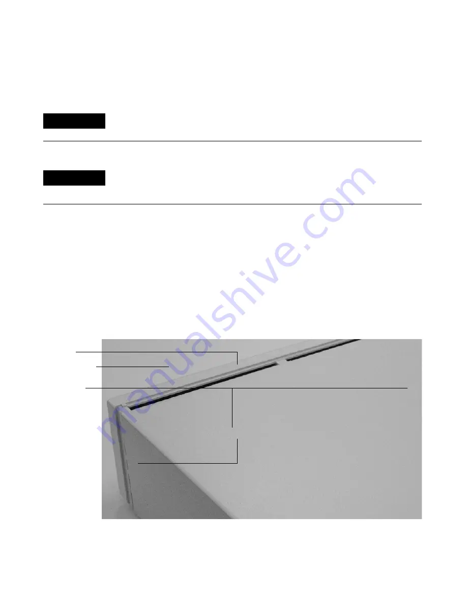
Remove the two screws attaching the top cover to the rear panel. (See
Figure 12 and Figure 15 on page 51.)
5
Lift up the back of the top cover and slide the lip of the cover over the
frame, slipping the front tabs under the front panel edge.
6
When you are ready to replace the top cover, fit the top cover over the
frame, slipping the front tabs under the front panel edge.
7
Push the cover firmly down until the screw holes are aligned.
8
Reattach the two screws on the back of the unit.
WA RN I N G
This procedure is intended for use by Agilent-trained service personnel only. There
are no user-serviceable parts inside the 35900.
WA RN I N G
When removing or replacing the subassembly inside the 35900, be certain the power
cord is unplugged from the rear of the unit in order to avoid a potentially dangerous
electrical shock.
Figure 12
Removing the top cover
Lip
Front panel
Screws
Power cord connection
Содержание Agilent 35900E
Страница 1: ...Agilent Technologies Agilent 35900E Dual Channel Interface User Manual ...
Страница 6: ...6 User Information Manual ...
Страница 36: ...36 User Manual 4 Instrument Connection ...
Страница 48: ...48 User Manual 6 Parts Replacement ...
Страница 51: ...Instrument Parts Breakdown 7 User Manual 51 Figure 15 Parts breakdown 1 2 3 4 5 ...
Страница 53: ...Instrument Parts Breakdown 7 User Manual 53 Figure 16 Parts breakdown inside the 35900 1 2 3 4 ...
Страница 54: ...54 User Manual 7 Instrument Parts Breakdown ...
Страница 60: ...60 User Manual A Cables ...


