background image

138

Installation and User’s Guide

F

Understanding the Bias Networks


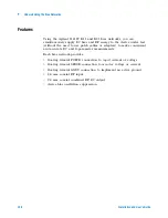
Features

Using the Agilent 11612V K11 and K21 bias networks, you can 
simultaneously supply DC bias and RF energy to the device under test 
(without the need to use patch cables or adapters) to make convenient 
and accurate DC and S- parameter measurements.

Each bias network provides:

floating triaxial FORCE connection to 

input

 current or voltage

floating triaxial SENSE connection to 

monitor

 voltage or current

floating triaxial GNDU connection to implement an active ground

2.4 mm coaxial RF input

2.4 mm coaxial combined RF/DC output

device bias oscillation suppression

Содержание 85225F

Страница 1: ...Agilent Technologies Agilent 85225F PerformanceModelingSystem Installation and User s Guide ...

Страница 2: ... terms covering the material in this document that conflict with these terms the warranty terms in the sep arate agreement shall control Technology Licenses The hardware and or software described in this document are furnished under a license and may be used or copied only in accordance with the terms of such license Restricted Rights Legend If software is for use in the performance of a U S Gover...

Страница 3: ...rmed or adhered to could result in personal injury or death Do not proceed beyond a WARNING notice until the indicated conditions are fully understood and met CAUTION A CAUTION notice denotes a hazard It calls attention to an operating procedure practice or the like that if not correctly performed or adhered to could result in damage to the product or loss of important data Do not proceed beyond a...

Страница 4: ...bols Definition Warning risk of electric shock Warning hot surface Caution refer to instrument documentation Laser radiation symbol marked on products that have a laser output Alternating current Both direct and alternating current Three phase alternating current Earth ground terminal Protective earth ground terminal Frame or chassis terminal Terminal is at earth potential Used for measurement and...

Страница 5: ...ol appears when it is necessary for the user to refer to the instruction in the documentation The CE mark is a registered trademark of the European Community This product complies with the WEEE Directive 2002 96 EC marking requirements The affixed label indicates that you must not discard this electrical electronic product in domestic household waste To return unwanted products contact your local ...

Страница 6: ...be impaired This product must be used only in a normal condition in which all means for protection are intact only WARNING DO NOT OPERATE IN AN EXPLOSIVE ATMOSPHERE Do not operate the instrument in the presence of flammable gases or flames WARNING DO NOT REMOVE THE INSTRUMENT COVER Operating personnel must not remove instrument covers Component replacement and internal adjustments must be made onl...

Страница 7: ...on of the protective grounding conductor or disconnection of the protective earth terminal will cause a potential shock hazard that could result in personal injury CAUTION Verify that the product is set to match the available line voltage the correct fuse is installed and all safety precautions are taken Before applying power note the product s external markings described in Table A Safety Symbols...

Страница 8: ...nt panel LINE switch disconnects the mains circuit from the mains supply However the mains supply to the power distribution unit remains energized WARNING For continued protection against fire hazard use only fuses with the required rated current voltage and specified type normal blow time delay Do not use repaired fuses or short circuited fuse holders Replace only with an identical fuse There are...

Страница 9: ...using criterion C where operator intervention may be necessary to restart the measurement software operations IEC EN 61326 Electrostatic Discharge and Surge Immunity Test This system complies with the Electrostatic Discharge and Surge Immunity requirements in the IEC EN 61326 standard using Performance Criterion C For Technical Assistance To receive technical assistance visit the online assistance...

Страница 10: ...ication and performing a post installation functional verification test using a system controller running IC CAP software 4 Servicing the System This chapter includes instruction on troubleshooting the system removing and replacing system components ordering replacement parts and acquiring additional assistance in solving measurement problems A Enhancing Measurement Accuracy See this appendix for ...

Страница 11: ...re F Understanding the Bias Networks Here you will find features characteristics a schematic diagram and operational information on the bias networks G Network Analyzer Performance Specification Summary See this appendix for a summary of the network analyzer s performance specifications For Additional Information on Hardware Additional information regarding instruments and accessories within the s...

Страница 12: ...ULUS key group Data field entries Enter Calset Enter 18 Enter Calset Enter 18 Keyboard keys Press Ctrl 8 Press Enter Press Ctrl 8 Press Enter Interface Examples in Body Text Examples in Procedural Text and Tables Screen buttons and selections Click Enter Select Continuous Click Enter Select Continuous Menu selections Choose Format Small Choose Cal Full Choose Format Small Choose Cal Full Command a...

Страница 13: ... 4156C 29 Table 6 Rear Panel System Connections with Agilent E5260A or E5270B 30 Figure 6 Rear Panel Wiring with Agilent E5260A or E5270B 31 Figure 7 DC RF Cabling Diagram DC and RF Configuration 32 CV RF and DC Measurement System Configuration 33 Figure 8 System Block Diagram 33 The CV Subsystem 34 Component Integration 34 Figure 9 System Components 35 Table 7 Front Panel System Connections 36 Fi...

Страница 14: ...em Controller 59 Table 13 Personal Computer Requirements 59 Table 14 UNIX Workstation Requirements 59 The Rack Cabinet 60 Performance Characteristics and Specifications 61 Table 15 Supplemental System Characteristics 61 Interference Standards 61 Performance Modeling System Performance Specifications 61 RF Subsystem Performance Specifications 62 DC Subsystem Specifications 62 Bias Network Character...

Страница 15: ... problem 101 4 Servicing the System To troubleshoot the system 104 To remove or replace a system component 105 To order replacement parts 106 To receive additional assistance 107 Table 19 Contacting Agilent Technologies 107 To package the system for transport 108 A Enhancing Measurement Accuracy To enhance measurement accuracy 112 Understanding System Measurement Calibration 114 Required Tools 114...

Страница 16: ...st 131 If you encounter a problem 132 E 1 f Noise Subsystem Functional Verification Test Understanding the 1 f Noise Subsystem Functional Verification Test 134 Required Tools 134 Performing the 1 f Noise Subsystem Functional Verification Test 135 If you encounter a problem 136 F Understanding the Bias Networks Features 138 Characteristics 139 Table 20 11612V Option K11 K21 Bias Network Characteris...

Страница 17: ... 33 1 f Noise CV RF and DC Measurement System Configuration 45 The System Controller 59 Performance Characteristics and Specifications 61 Related Topics Installing the System on page 63 Network Analyzer Performance Specification Summary on page 141 Understanding the Bias Networks on page 137 Use this chapter to familiarize yourself with the measurement configurations of the performance modeling sy...

Страница 18: ...modeling system to measure CV and 1 f noise with the addition of optional instrumentation and IC CAP 1 f noise measurement modules For RF and DC performance measurement system configurations see RF and DC Measurement System Configuration on page 19 For CV RF and DC performance measurement system configurations see CV RF and DC Measurement System Configuration on page 29 For 1 f noise CV RF and DC ...

Страница 19: ...f active and passive devices The IC CAP software then extracts the device parameters and displays the results The Agilent 85225F performance modeling system is the integration of rack mounted RF and DC subsystems bias networks and a system controller as shown in Figure 1 The system controller is not included and must be provided This block diagram shows a system with an Agilent 4156C as the DC sub...

Страница 20: ...SMUs high resolution source monitor units Optionally the Agilent 4156C may be configured with a 41501B SMU PGU expander is connected to and controlled by the 4156C via the expander box interface The 41501B provides a GNDU active ground unit and depending on option configuration an HPSMU high power source monitor unit two MPSMUs medium power source monitor units and or two PGUs pulse generator unit...

Страница 21: ... up to 100 volts of potential and 200 milliamps of current to the device under test The Bias Networks The Agilent 11612V Option K11 and K21 bias networks combine the DC and RF signals and apply them simultaneously to the device under test DUT The bias networks are configured with 2 4 mm DC RF output connectors for connection to a DUT a test fixture or probe station as shown in Figure 21 on page 54...

Страница 22: ... or optionally Agilent E5260A or E5270B Agilent 11612V Option K11 bias network port 1 Agilent 11612V Option K21 bias network port 2 Agilent 85133F flexible test port cable set Agilent E3661B 1 6 meter rack cabinet filler panels feedthrough panels work surface cables and adapters For systems with Agilent 4156C front panel connections are listed in Table 3 on page 24 and illustrated in Figure 3 on p...

Страница 23: ...Introducing the Agilent 85225F Performance Modeling System 1 Installation and User s Guide 23 Figure 2 System Components ...

Страница 24: ...riaxial cable Triax BNC 4156C HRSMU1 SENSE DC SENSE 11612V K11 2 16494A Option 002 Triaxial cable Triax BNC 4156C HRSMU1 FORCE DC FORCE 11612V K11 3 16494A Option 002 Triaxial cable Triax BNC 4156C HRSMU2 SENSE DC SENSE 11612V K21 4 16494A Option 002 Triaxial cable Triax BNC 4156C HRSMU2 FORCE DC FORCE 11612V K21 5 16494A Option 002 Triaxial cable Triax BNC 4156C HRSMU3 FORCE GNDU 11612V K21 6 851...

Страница 25: ...Introducing the Agilent 85225F Performance Modeling System 1 Installation and User s Guide 25 Figure 3 Front Panel Connections with Agilent 4156C ...

Страница 26: ...cable Triax BNC E5260A 70B HPSMU1 SENSE DC SENSE 11612V K21 2 16494A Option 002 Triaxial cable Triax BNC E5260A 70B HPSMU1 FORCE DC FORCE 11612V K21 3 16494A Option 002 Triaxial cable Triax BNC E5260A 70B MPSMU3 FORCE DC FORCE 11612V K11 4 16494A Option 002 Triaxial cable Triax BNC E5260A 70B MPSMU3 SENSE DC SENSE 11612V K11 5 16493L Option 002 Triaxial GNDU cable Triax BNC E5260A 70B GNDU GNDU GN...

Страница 27: ...Introducing the Agilent 85225F Performance Modeling System 1 Installation and User s Guide 27 Figure 4 Front Panel Wiring Diagram with Agilent E5260A or E5270B ...

Страница 28: ...DC FORCE 11612V K21 2 16494A Option 002 Triaxial cable Triax BNC 4156C HRSMU2 SENSE DC SENSE 11612V K21 3 16494A Option 002 Triaxial cable Triax BNC 4156C HRSMU1 FORCE DC FORCE 11612V K11 4 16494A Option 002 Triaxial cable Triax BNC 4156C HRSMU1 SENSE DC SENSE 11612V K11 5 16494A Option 002 Triaxial cable Triax BNC 4156C HRSMU3 FORCE GNDU 11612V K21 6 10833D GPIB cable GPIB 4156C GPIB GPIB E8364B ...

Страница 29: ...Introducing the Agilent 85225F Performance Modeling System 1 Installation and User s Guide 29 Figure 5 Rear Panel Wiring Diagram with Agilent 4156C ...

Страница 30: ...tion Table 6 Rear Panel System Connections with Agilent E5260A or E5270B Component Information Connection Information Designator Model Number Description Connector Type From Instrument Connector Labeled ToConnector Labeled On Instrument 1 10833A GPIB cable GPIB 4156C GPIB GPIB E8364B 2 10833C GPIB cable GPIB E8364B GPIB GPIB Controller ...

Страница 31: ...Introducing the Agilent 85225F Performance Modeling System 1 Installation and User s Guide 31 Figure 6 Rear Panel Wiring with Agilent E5260A or E5270B ...

Страница 32: ...tallation and User s Guide 1 Introducing the Agilent 85225F Performance Modeling System Figure 7 DC RF Cabling Diagram DC and RF Configuration Systems with Agilent 4156C Systems with Agilent E5260A or E5270B ...

Страница 33: ...F performance modeling system measures the DC RF and CV performance of active and passive devices The IC CAP software then extracts the device parameters and displays the results The Agilent 85225F performance modeling system for CV RF and DC measurement is the integration of rack mounted RF DC and CV subsystems bias networks and a system controller as shown in Figure 8 Figure 8 System Block Diagr...

Страница 34: ...m component integration is performed at the Agilent Technologies factory The individual components are placed into the rack and the required cabling is connected between the instruments After factory integration the system is tested to verify functional performance The Agilent 85225F performance modeling system includes the following components as shown in Figure 18 on page 49 Agilent E8364B PNA S...

Страница 35: ...Introducing the Agilent 85225F Performance Modeling System 1 Installation and User s Guide 35 Figure 9 System Components ...

Страница 36: ...E 11612V K11 2 16494A Option 002 Triaxial cable Triax BNC 4156C HRSMU1 SENSE DC SENSE 11612V K11 3 16494A Option 002 Triaxial cable Triax BNC 4156C HRSMU2 FORCE DC FORCE 11612V K21 4 16494A Option 002 Triaxial cable Triax BNC 4156C HRSMU2 SENSE DC SENSE 11612V K21 5 16494A Option 002 Triaxial GNDU cable Triax BNC 4156C HRSMU3 FORCE GNDU 11612V K21 6 85133F Flexible test port cable 2 4 mm E8364B PO...

Страница 37: ...Introducing the Agilent 85225F Performance Modeling System 1 Installation and User s Guide 37 Figure 10 Front Panel Wiring Diagram ...

Страница 38: ...e Triax BNC 4156C HRSMU1 FORCE DC FORCE 11612V K11 2 16494A Option 002 Triaxial cable Triax BNC 4156C HRSMU1 SENSE DC SENSE 11612V K11 3 16494A Option 002 Triaxial cable Triax BNC 4156C HRSMU2 FORCE DC FORCE 11612V K21 4 16494A Option 002 Triaxial cable Triax BNC 4156C HRSMU2 SENSE DC SENSE 11612V K21 5 16494A Option 002 Triaxial cable Triax BNC 4156C HRSMU3 FORCE GNDU 11612V K21 6 10833D GPIB cab...

Страница 39: ...Introducing the Agilent 85225F Performance Modeling System 1 Installation and User s Guide 39 Figure 11 Rear Panel Wiring Diagram ...

Страница 40: ...40 Installation and User s Guide 1 Introducing the Agilent 85225F Performance Modeling System Figure 12 DC RF Cabling Diagram DC and RF Configuration ...

Страница 41: ...Introducing the Agilent 85225F Performance Modeling System 1 Installation and User s Guide 41 Figure 13 DC RF Cabling Diagram Parametric Configuration ...

Страница 42: ...onnector Type From Instrument Connector Labeled ToConnector Labeled On Instrument 1 16494A Option 002 Triaxial cable Triax BNC 4156C HRSMU1 SENSE SMU INPUT 2 E5250A 2 16494A Option 002 Triaxial cable Triax BNC 4156C HRSMU1 FORCE SMU INPUT 1 E5250A 3 16494A Option 002 Triaxial cable Triax BNC 4156C HRSMU2 FORCE SMU INPUT 3 E5250A 4 16494A Option 002 Triaxial cable Triax BNC 4156C HRSMU2 SENSE SMU I...

Страница 43: ...Introducing the Agilent 85225F Performance Modeling System 1 Installation and User s Guide 43 Figure 14 Rear Panel Wiring Diagram including Low Leakage Switch Mainframe ...

Страница 44: ...44 Installation and User s Guide 1 Introducing the Agilent 85225F Performance Modeling System Figure 15 DC RF Cabling Diagram Parametric Configuration with Low Leakage Switch Mainframe ...

Страница 45: ...ter the Agilent 85225F performance modeling system measures the DC RF CV and 1 f noise performance of active and passive devices The IC CAP software then extracts the device parameters and displays the results The Agilent 85225F performance modeling system is the integration of rack mounted RF and DC subsystems a precision LCR meter a dynamic signal analyzer bias networks and a system controller a...

Страница 46: ...h a customer furnished Stanford Model SR570 low noise amplifier measures the flicker noise 1 f noise of active devices Controlled by IC CAP device modeling software the dynamic signal analyzer generates reliable 1 f noise measurement data which are analyzed and extracted in IC CAP Figure 17 shows the system configuration for 1 f noise measurements Figure 16 System Block Diagram ...

Страница 47: ...Introducing the Agilent 85225F Performance Modeling System 1 Installation and User s Guide 47 Figure 17 1 f Noise Measurement Block Diagram ...

Страница 48: ...lent 4156C precision semiconductor parameter analyzer with optional Agilent 41501B SMU PGU expander or optionally Agilent E5260A or E5270B Agilent 11612V Option K11 bias network port 1 Agilent 11612V Option K21 bias network port 2 Agilent 4284A precision LCR meter Agilent 35670A dynamic signal analyzer Stanford Research SR 570 low noise current amplifier Agilent 85133F flexible test port cable set...

Страница 49: ...Introducing the Agilent 85225F Performance Modeling System 1 Installation and User s Guide 49 Figure 18 System Components ...

Страница 50: ... Triaxial cable Triax BNC 41501B HPSMU SENSE DC SENSE 11612V K11 3 16494A Option 002 Triaxial cable Triax BNC 4156C HRSMU1 FORCE DC FORCE 11612V K21 4 16494A Option 002 Triaxial cable Triax BNC 4156C HRSMU1 SENSE DC SENSE 11612V K21 5 16493L Option 002 Triaxial GNDU cable Triax BNC 41501B GNDU GNDU 11612V K21 6 85133F Flexible test port cable 2 4 mm E8364B PORT 1 RF IN 11612V K11 7 85133F Flexible...

Страница 51: ...Introducing the Agilent 85225F Performance Modeling System 1 Installation and User s Guide 51 Figure 19 Front Panel Wiring Diagram ...

Страница 52: ... HRSMU1 FORCE DC FORCE 11612V K11 2 16494A Option 002 Triaxial cable Triax BNC 4156C HRSMU1 SENSE DC SENSE 11612V K11 3 16494A Option 002 Triaxial cable Triax BNC 41501B HPSMU FORCE DC FORCE 11612V K21 4 16494A Option 002 Triaxial cable Triax BNC 41501B HPSMU SENSE DC SENSE 11612V K21 5 16493L Option 002 GNDU cable Triax BNC 41501B GNDU GNDU 11612V K21 6 10833A GPIB cable GPIB 4156C GPIB GPIB 4284...

Страница 53: ...Introducing the Agilent 85225F Performance Modeling System 1 Installation and User s Guide 53 Figure 20 Rear Panel Wiring Diagram ...

Страница 54: ...54 Installation and User s Guide 1 Introducing the Agilent 85225F Performance Modeling System Figure 21 DC RF Cabling Diagram DC and RF Configuration ...

Страница 55: ...Introducing the Agilent 85225F Performance Modeling System 1 Installation and User s Guide 55 Figure 22 DC RF Cabling Diagram Parametric Configuration ...

Страница 56: ...9 The 4156C default GPIB address 17 is sometimes used by other devices with a GPIB address at 16 for example an external display set to 17 to display the results generated by an instrument at address 16 Change the 4156C GPIB address to 19 using the procedure described in step 13 of To switch on power to the system on page 87 to ensure that IC CAP can recognize the 4156C Agilent 4284A precision LCR...

Страница 57: ... over an existing local area network It allows the use of SICL or VISA based applications designed for GPIB over the LAN without modifying the application beyond a simple address change The gateway is a combination of hardware and SICL VISA software It uses client server technology to extend the standard remotely over the LAN allowing remote control from an alternative more convenient or safer loc...

Страница 58: ...58 Installation and User s Guide 1 Introducing the Agilent 85225F Performance Modeling System Figure 23 Rear Panel Wiring Diagram for LAN GPIB Gateway ...

Страница 59: ...Recommended file systems are FAT32 and NTFS Novell file servers are not supported VFAT FAT systems are not recommended for full installations RAM 128 megabytes additional RAM will improve software performance Virtual memory 300 megabytes Increased virtual memory may be required For NT 4 0 only to avoid potential memory problems ensure your virtual memory space is always greater than your RAM space...

Страница 60: ...he system instrumentation A rack mounted work surface is included for maximum flexibility and convenience in making in fixture or coaxial measurements The work surface can be removed to facilitate on wafer measurements using a probe station The work surface is coated with antistatic material and connected to chassis ground Therefore an antistatic mat is not required For installation instructions s...

Страница 61: ...s The Agilent 85225F performance modeling system adheres to the performance specifications of an Agilent E8364B PNA Series vector network analyzer Refer to Appendix G Network Analyzer Performance Specification Summary starting on page 141 Table 15 Supplemental System Characteristics Characteristic Value Line voltage 115 volts nominal 90 volts to 132 volts or 220 volts nominal 210 volts to 250 volt...

Страница 62: ...er are listed in its user s guide chapter 7 of Volume 1 General Information Specifications for the Agilent E5260A 8 slot high speed measurement mainframe and Agilent E5270B 8 slot precision parametric measurement mainframe are listed in its user s guide Chapter 2 Introduction Bias Network Characteristics Table 20 11612V Option K11 K21 Bias Network Characteristics on page 139 lists the operational ...

Страница 63: ...onnect the bias networks 80 To switch on power to the system 87 This completes the installation process To confirm the functionality of the system continue to Chapter 3 Verifying System Functionality starting on page 91 89 Related Topics Introducing the Agilent 85225F Performance Modeling System on page 17 Use this chapter to learn how to first prepare the installation site and then receive unpack...

Страница 64: ...ture 0 C to 45 C 32 F to 113 F Install air conditioning and heating as needed to achieve the required ambient temperature range Accuracy enhanced measurement performance is specified at an ambient temperature range of 25 C 5 C After calibration hold the ambient temperature of the measurement environment to 1 C of the ambient temperature at the time of calibration Relative humidity Maximum 80 for t...

Страница 65: ...on To unpack the shipment crate containing the rack cabinet on page 66 Keep all cartons and packaging material until the entire shipment has been verified undamaged and complete and the system has passed visual inspection and functional verification 2 If the system is damaged notify appropriate parties a Report the shipment damage to your Agilent Technologies sales representative b Report the ship...

Страница 66: ...tem is repacked To unpack the shipment crate containing the rack cabinet Step Action Notes 1 Remove the outer packing crate a Remove the clamps holding the packing crate top cover in place b Remove the top cover and set it aside c Remove the clamps holding the first packing crate wall in place d Insure that two other people are available to hold the last two walls in place as the last set of clamp...

Страница 67: ... that the cabinet casters are rolling freely h Roll the system down the ramp using extreme care i Carefully roll the rack toward its prepared place within the measurement environment In case the system must be moved in the future retain and reuse these packing materials You can also purchase replacement packing materials from Agilent Technologies To unpack the shipment crate containing the rack ca...

Страница 68: ...h the exception of the bias networks semi rigid and SMU triaxial cables all other cables are connected at the factory NOTE Other cables and accessories are shipped inside the rack mounted storage drawer To verify the shipment Step Action Notes 1 Verify that the serial numbers on the rear panel of the system instruments match the serial numbers listed in the shipping documentation Compare the seria...

Страница 69: ... To receive additional assistance on page 107 Table 18 Replaceable Parts Part or Model Number Description 10833A GPIB cable 1 meter 10833B GPIB cable 2 meter 10833C GPIB cable 4 meters 10833D GPIB cable 0 5 meter 11612T Option K33 Mounting plates bias networks to probe station 11612V Option K11 Bias network port 1 45 MHz to 50 GHz 0 5 A 11612V Option K21 Bias network port 2 45 MHz to 50 GHz 0 5 A ...

Страница 70: ...bles 41501B Option 420 Add 2 medium power SMUs and cables 41501B Option 422 Add 2 medium power SMUs 2 PGUs and cables 41501B Option 902 Cable power Europe 41501B Option 903 Cable power US and Canada 4156C Precision semiconductor parameter analyzer 4156C Option 010 Delete all 4156C cables 4156C Option 020 Delete Windows controller for parameter analysis and characterization 4156C Option 200 1 5 met...

Страница 71: ...houlder screw 85043 80013 Anti static mat kit 85056A Precision calibration kit 2 4 mm 85056D Economy calibration kit 2 4 mm 85106 60038 Work surface 1 meter 85107 20004 Semi rigid cable 9 inch 2 4 mm m m 85133F 2 4 mm flexible test port cable set 85225 90023 Agilent 85225F Performance Modeling System Installation and User s Guide C2790AC Ballast 30 pounds E3661B Rack cabinet 1 6 meter E3661B Optio...

Страница 72: ...n ABJ Japanese localization E5280A Precision high power source monitor unit E5281A Precision medium power source monitor unit E5286A High resolution source monitor unit E5810A LAN GPIB gateway E5810A Option 100 Rack mount kit E5810A Option AG6 I O libraries client software for MS Windows E5810A Option ABJ Japanese documentation E7731A Filler panel 1 EIA unit E7732A Filler panel 2 EIA unit E7733A F...

Страница 73: ... Option 081 Reference receiver switch E8364B Option 083 Frequency converter measurement application E8364B Option 1CP Rack mount kit with handles E8364B Option H08 Pulsed RF measurement capability E8364B Option H11 IF access E8364B Option UNL Extended power range Table 18 Replaceable Parts continued Part or Model Number Description ...

Страница 74: ...he bottom of the rack cabinet b Unpack the work surface and the work surface support rails c Lay the rails down so that the ends with the single pemmed hole are facing the front the ends with the keyhole shaped cutout are facing the rear and the rails are facing inward toward each other The lock feet prevent the cabinet from moving on the casters These are the positions of the support rails when i...

Страница 75: ...Slide the work surface onto the support rails b Slide the work surface all the way back on the rails until it comes to rest against the front of the rack cabinet c Use 1 2 inch long 10 32 screws to secure the work surface to the rails from the beneath To install the work surface continued Step Action Notes ...

Страница 76: ...tep Action Notes 1 Never operate the system without a safety earth ground a Ensure that a safety earth ground is connected between the system power distribution unit and the line power source b If it is likely that the safety earth ground has been impaired the system must be rendered inoperative and secured against unintended operation Capacitors within the system components can remain charged eve...

Страница 77: ...ot lit Deactivate the standby mode if used by pressing the Standby key and confirming that the Standby indicator is not lit Confirm that the HIGH VOLTAGE indicator is not lit Open the interlock connection 6 Never use replacement fuses with incorrect ratings a After finding the cause of failure replace component fuses with fuses of the same current rating and of the type specified in the instrument...

Страница 78: ...ar connecting the CIRCUIT COMMON and CHASSIS GROUND terminals When the shorting bar is removed you must drive the DUT circuit common with either an SMU GNDU or by connecting directly to the DC subsystem circuit common The circuit common can be found at the DUT ends of the SMU and GNDU cables Read Precautions for Performing Floating Ground Measurements on page 78 then follow these steps to connect ...

Страница 79: ...tatic discharge that could damage the system or the device under test CAUTION Even relatively small currents resulting from electrostatic discharge undetectable to the system operator can damage current sensitive devices and system components To take precautions against electrostatic discharge Step 1 Wear an antistatic wrist strap 2 Connect the wrist strap to chassis ground ...

Страница 80: ...the triaxial cables from the 4156C to the bias networks a Connect the triaxial cables from the 4156C HRSMU1 FORCE and SENSE connectors to the DC FORCE and DC SENSE connectors on the port 1 bias network b Connect the triaxial cables from the 4156C HRSMU2 FORCE and SENSE connectors to the DC FORCE and DC SENSE connectors on the port 2 bias network From the rear of the system route the cable through ...

Страница 81: ...as network d Connect one end of the port 2 test port cable to the Agilent E8364B test port 2 e Connect the other end of the test port 2 test port cable to the 2 4 mm male to male adapter f Connect the other end of the 2 4 mm male to male adapter to the RF IN connector of the 11612V K21 bias network The test port cables model number is 85133F The 2 4 mm female to male adapter model number is 11900C...

Страница 82: ...ort 2 bias network From the rear of the system route the cable through the feedthrough panel The port 1 bias network is the 11612V K11 The port 2 bias network is the 11612V K21 Refer to Figure 20 Rear Panel Wiring Diagram on page 53 3 Connect and route the triaxial cable from 4156C HRSMU3 FORCE connector to the port 2 bias network a From the rear of the system connect one end of the triaxial cable...

Страница 83: ...ter to the RF IN connector of the 11612V K21 bias network The test port cables model number is 85133F The 2 4 mm female to male adapter model number is 11900C Without this adapter the test port cable will not properly mate with the bias network RF IN connector The 2 4 mm male to male adapter model number is 11900A 5 Connect the bias networks to the device under test a Connect one semi rigid cable ...

Страница 84: ...l medium power SMU FORCE and SENSE outputs on the E5260A 70B c From the front of the system route the cable through the upper feedthrough panel d From the rear of the system route the HPSMU cable through the port 2 hole in the lower feedthrough panel e From the rear of the system route the MPSMU cable through the port 1 hole in the lower feedthrough panel The triaxial cable model number is 16494A ...

Страница 85: ... feedthrough panel d Connect the ground triaxial cable to the port 2 bias network GNDU connector The ground triaxial cable model number is 16493L Option 002 Leave the GNDU connector on the port 1 bias network open 5 Connect the Agilent E8364B test ports to the bias networks a Connect one end of the port 1 test port cable to the Agilent E8364B test port 1 b Connect the other end of the test port 1 ...

Страница 86: ...e to the RF DC OUT connector of the port 2 bias network c Connect the device under test to the semi rigid cable attached to the port 1 bias network d Connect the device under test to the semi rigid cable attached to the port 2 bias network The semi rigid cables part number is 85107 20004 Refer to Figure 4 Front Panel Wiring Diagram with Agilent E5260A or E5270B on page 27 To connect the bias netwo...

Страница 87: ...EM CONFIG page highlight the value in the GPIB ADDRESS field and press 24 Enter This sets the correct system GPIB address 24 for the 4284A 8 If present on the 35670A front panel press Local GPIB ANALYZER ADDRESS 22 ENTER This sets the correct system GPIB address 22 for the 35670A 9 If present switch on the Agilent 4156C precision semiconductor parameter analyzer line power 10 If present switch on ...

Страница 88: ...e power 16 On the Agilent E8364B PNA Series vector network analyzer from the Main dialog select System Configure SICL GPIB In the SICL GPIB dialog GPIB group box select the Talker Listener radio button and select 16 in the Address scroll list This sets the correct system GPIB address 16 for the E8364B 17 If present switch on the LAN GPIB gateway line power Refer to the LAN GPIB gateway documentati...

Страница 89: ...he performance modeling system To configure the LAN GPIB gateway Step Action Notes 20 Start the IC CAP software To familiarize yourself with the IC CAP software refer to the first three chapters of the Agilent IC CAP 2004 User s Guide model number 85190D PC version a Select Start Programs IC CAP 2004 IC CAP UNIX version a Open a UNIX terminal window b At the prompt type iccap c Press Enter This st...

Страница 90: ...90 Installation and User s Guide 2 Installing the System ...

Страница 91: ...ment accuracy on page 112 Performing a Coaxial System Measurement Calibration on page 115 Performing the DC Subsystem Functional Verification Test on page 121 Performing the RF Subsystem Functional Verification Test on page 125 Use the procedures in this chapter to verify the functionality of the Agilent 85225F performance modeling system This chapter includes procedures for choosing varying degre...

Страница 92: ...nal Verification Test starting on page 133 Follow these steps to choose a system functional verification process based upon your current situation NOTE These tests do NOT verify that the system instrumentation conform to their individual performance specifications To verify the performance of the individual system components complete the appropriate performance tests listed in their individual pro...

Страница 93: ...g the GPIB interface Complete the steps listed in Performing the DC Subsystem Functional Verification Test on page 121 5 If you would like to manually check the functionality of the Agilent 4284A without using the GPIB interface Complete the steps listed in Performing the CV Subsystem Functional Verification Test on page 131 6 If you would like to manually check the functionality of the Agilent 35...

Страница 94: ... data the IC CAP software can converge the simulated data with the extracted measured data The system applies forward and reverse current to the attenuator and monitors voltage at the attenuator s input and output IC CAP then uses the measured data to model the device intrinsic resistances and transmission line delay Required Tools Agilent 85225F performance modeling system A system controller Agi...

Страница 95: ...e order in which the system components are switched on 2 Connect the device under test to the bias networks a Refer to the following figure b Connect one end of the 2 4 mm female to female adapter to the semi rigid cable attached to the RF DC OUT connector of the port 1 bias network c Connect male end of the attenuator to the other end of the 2 4 mm female to female adapter d Connect the female en...

Страница 96: ...4156 window Unit Table group box highlight the characters in the HRSMU1 entry box and type VG c In the Unit Table group box highlight the characters in the HPSMU entry box and type VD d Click OK e Close the Hardware Setup window This opens the Configuration of HP4156 window where the Unit Table dialog box is used to change the names of the HRSMUs Actions b c and d change the name of HRSMU1 to VG a...

Страница 97: ...t variable and enter 4 5E 07 c Highlight the freq_stop variable and enter 50E 09 d Highlight the imax variable and enter 90m This opens the Model Variables tab folder This sets the start frequency of the model to 45 MHz This sets the stop frequency of the model to 50 GHz This sets the maximum current to 90 milliamps 9 Set the network analyzer instrument options for the attenuator test model in IC ...

Страница 98: ...on test macro 11 Calibrate the network analyzer a In the network analyzer s Calibration menu select Calibration Wizard b In the Calibration Wizard Begin Calibration dialog box select SmartCal GUIDED Calibration Use Mechanical Standards radio button and click Next c Follow the displayed prompts to calibrate the network analyzer For detailed instructions see Performing a Coaxial System Measurement C...

Страница 99: ...ults a Observe the displayed plots b In the IC CAP Status window observe the final DC RF values parameter and the Final RMS error When the S parameter measurement is complete IC CAP displays plots of the S12 21 20 log10 of the S21 magnitude and S21 phase IC CAP also lists the attenuator s resistance values The error between measured and simulated data should be less than 2 The error between the me...

Страница 100: ...le and enter 2 This sets the cable length in the LCR meter instrument options 18 Calibrate the LCR meter a On the 16048D test leads connect one tee between the Hpot and Hcur connectors b Connect the other tee between the Lpot and Lcur connectors Select the Measure Simulate tab c Select Calibrate d Follow the IC CAP prompts This performs a calibration on the LCR meter The BNC tee part number is 125...

Страница 101: ...ystem Functional Verification Test starting on page 119 Perform the Agilent E8364B PNA Series vector network analyzer operator s check in Appendix C RF Subsystem Functional Verification Test starting on page 123 Perform the Agilent 4284A precision LCR meter self test in Appendix D CV Subsystem Functional Verification Test starting on page 129 Perform the Agilent 35670A dynamic signal generator sel...

Страница 102: ...102 Installation and User s Guide 3 Verifying System Functionality ...

Страница 103: ... Contacting Agilent Technologies 107 To package the system for transport 108 Related Topics Performing the System Functional Verification Test on page 95 Component Integration on page 48 Use this chapter to solve problems This chapter includes a checklist for troubleshooting the system a procedure for removing a system component from the rack cabinet information on ordering replacement parts and a...

Страница 104: ...n Performing the DC Subsystem Functional Verification Test on page 121 Complete the Agilent 4284A self test by cycling the instrument s line power If errors occur refer to Appendix B in the precision LCR meter operation manual The operation manual is included in with the Agilent 85225F performance modeling system If you suspect trouble with the E2050B see Chapter 4 Troubleshooting in the E5810A LA...

Страница 105: ... opening covers or removing parts To remove a system component Step Note 1 Turn off all components 2 Disconnect the system from line power 3 Disconnect all cables from the instrument to be removed 4 Prepare a surface near the rack cabinet to place the removed system component 5 Lower the stabilizing legs on the rack cabinet 6 From the front of the rack cabinet remove the four screws 2 screws on ea...

Страница 106: ...the System Functional Verification Test on page 95 To order replacement parts To find the part or model number of a replaceable system component refer to Table 18 Replaceable Parts on page 69 To order contact Agilent Technologies by calling the telephone number listed in Table 19 on page 107 appropriate to the location of the modeling system ...

Страница 107: ...g Kong tel 800 930 871 fax 852 2506 9233 India tel 1 600 11 2929 fax 000 800 650 1101 Japan tel 81 426 56 7832 fax 81 426 56 7840 Latin America tel 305 269 7500 fax 305 269 7599 Malaysia tel 1 800 828 848 fax 1 800 801 New Zealand tel 0 800 738 378 fax 64 4 495 8950 People s Republic of China tel 800 810 0189 preferred tel 10800 650 0021 fax 110800 650 0121 Philippines tel 632 8426802 fax 632 8426...

Страница 108: ...g retaining piece back to original position 8 Secure retaining piece with bolt 9 Secure rack cabinet to base using retaining brackets inserted in the slot located on each side of the packaging base 10 Secure retaining brackets with bolt and tighten 11 Place antistatic bag over rack cabinet 12 Place cardboard foam top cap on top of rack cabinet 13 Place folded ramp on top cap 14 Place crate side pa...

Страница 109: ...cing the System 4 Installation and User s Guide 109 17 Add tip indicators and appropriate labeling 18 Secure crate to packaging base using band straps To package the system for transport continued Step Note ...

Страница 110: ...110 Installation and User s Guide 4 Servicing the System ...

Страница 111: ...em Measurement Calibration 114 Performing a Coaxial System Measurement Calibration 115 If you encounter a problem 116 Periodic System Component Calibration 117 Related Topics Performing the System Functional Verification Test on page 95 Performing the RF Subsystem Functional Verification Test on page 125 Use the procedures in this appendix to enhance the accuracy of your measurements ...

Страница 112: ...efore activating the system Be careful not to let the alcohol get on the insulator bead as this may damage the bead Be careful not to exert too much force on the center conductors as they may be damaged Compressed air can reduce the temperature of connectors dramatically and this can have a significant effect upon the performance of calibration and verification components If the connector componen...

Страница 113: ... 85056D 2 4 mm economy calibration kit Use the Agilent 85033E 3 5 mm economy calibration kit Use the Agilent 85052D 3 5 mm economy calibration kit Torque measurement connections using the torque wrench provided in the calibration kit 6 Calibrate the system components at regular intervals a Every 6 to 12 months Perform the required Agilent E8364B PNA Series vector network analyzer performance verif...

Страница 114: ...em measurement calibration prior to measuring a device Performing a measurement calibration has no effect upon random errors To increase the accuracy of your measurements perform a system measurement calibration before performing device measurements Repeat the measurement calibration if the ambient temperature of the measurement environment has deviated 1 C since the last measurement calibration T...

Страница 115: ...nalyzer press Preset 2 Open the Calibration Wizard and choose a guided calibration a In the network analyzer s Calibration menu select Calibration Wizard b In the Calibration Wizard dialog box select Use Mechanical Stds in the Guided Calibrations group box 3 Choose the DUT connector types a In the Guided Calibration Select DUT Connectors dialog box select the appropriate DUT connector type for the...

Страница 116: ...ect the standard broadband load to the Port 1 bias network RF DC OUTPUT f Click Measure g Repeat actions a through f for the Port 2 calibration measurements h Follow the prompts to connect the standard through between the Port 1 and Port 2 bias networks RF DC OUTPUT connectors i Click Measure j When the measurements are done in the Standards Measured dialog box click Next k In the Guided Calibrati...

Страница 117: ...lyzer performance verification Agilent E5260A 70B precision parametric measurement solution performance verification Agilent 4284A precision LCR meter performance tests Agilent 35670A dynamic signal analyzer performance verification Agilent E5250A low leakage switch mainframe performance tests See the individual instrument documentation for instructions on performing the required instrument verifi...

Страница 118: ...118 Installation and User s Guide A Enhancing Measurement Accuracy ...

Страница 119: ...ncounter a problem 121 Related Topics Performing the System Functional Verification Test on page 95 Performing the RF Subsystem Functional Verification Test on page 125 Performing the CV Subsystem Functional Verification Test on page 131 Performing the 1 f Noise Subsystem Functional Verification Test on page 135 Use this appendix to perform a DC subsystem functional verification test using the Agi...

Страница 120: ...systems the internal operation of the Agilent 4156C precision semiconductor parameter analyzer For Agilent E5260A 70B DC subsystems the operation of the Agilent E5260A 70B parametric measurement mainframe the operation of the plug in source monitor units This procedure runs a self test initiated from the instrument s front panel The test includes a self calibration routine to improve short term ac...

Страница 121: ...l for the Agilent 4156C precision semiconductor parameter analyzer To perform the Agilent 4156C precision semiconductor parameter analyzer self test Step Notes 1 Disconnect all cables from the measurement terminals on the 4156C rear panel 2 Connect the 4156C to line power 3 Switch on the instrument line power switch 4 Wait 1 hour before continuing to step 5 5 Press System CALIB DIAG The analyzer d...

Страница 122: ...ecision parametric measurement solution self test Step Notes 1 Disconnect all cables from the measurement terminals on the E5260A 70B front panel 2 Connect the E5260A 70B to line power 3 Switch on the instrument line power switch 4 Wait 1 hour before continuing to step 5 5 Press Shift Menu 6 Move the cursor to SELFTEST and press Enter Move the cursor to EXECUTE and press Enter 7 Use the arrow keys...

Страница 123: ...l Verification Test 125 If you encounter a problem 127 Related Topics Performing the System Functional Verification Test on page 95 Performing the DC Subsystem Functional Verification Test on page 121 Performing the CV Subsystem Functional Verification Test on page 131 Performing the 1 f Noise Subsystem Functional Verification Test on page 135 Use the instructions in this appendix to perform a man...

Страница 124: ...ries vector network analyzer system This procedure does not verify performance to specification This procedure confirms that the network analyzer is ready for performance verification and or operation by confirming the following hardware functionality the repeatability of the RF switch in the test set the attenuation range of the test port attenuators Required Tools Agilent E8364B PNA Series vecto...

Страница 125: ...1 and click OK g Check PASS FAIL status h Continue to follow the prompts for the Attenuator Range tests i Check PASS FAIL status for each attenuator range j Click Start Port 2 k Repeat actions e through i for Port 2 l Click Exit to end the Operator s Check This opens the Operator s Check window This selects automatic program execution To enable a prompted test sequence choose Prompted to place a p...

Страница 126: ...t the reverse transmission mode for channel 1 a From the Trace drop down menu point to Measure and click S12 b Inspect the trace shown on the display It should be similar to the trace shown to the right 7 Test the reverse reflection mode for channel 1 a From the Trace drop down menu point to Measure and click S22 b Inspect the trace shown on the display It should be similar to the trace shown to t...

Страница 127: ...lation and User s Guide 127 If you encounter a problem Check the GPIB cable and connection Check the GPIB address Consult the Troubleshooting chapter of the Agilent E8364B PNA Series vector network analyzer service guide for troubleshooting information ...

Страница 128: ...128 Installation and User s Guide C RF Subsystem Functional Verification Test ...

Страница 129: ... Performing the CV Subsystem Functional Verification Test 131 If you encounter a problem 132 Related Topics Performing the System Functional Verification Test on page 95 Performing the RF Subsystem Functional Verification Test on page 125 Performing the DC Subsystem Functional Verification Test on page 121 Use the instructions in this appendix to perform a manual CV subsystem functional verificati...

Страница 130: ...recision LCR meter This procedure does not verify performance to specification This procedure confirms that the precision LCR meter is ready for performance verification and or operation by confirming the following hardware functionality memory card read write test LED display test LCD display test handler I F test scanner I F EEPROM read write test scanner I F I O test bias current I F I O test R...

Страница 131: ...otes 1 Activate the precision LCR meter a Connect the precision LCR meter to line power b Switch on the line power 2 Warm up the network analyzer for 1 hour a Wait 1 hour before continuing to step 3 3 Run the required self tests a On the precision LCR meter front panel press CATALOG SYSTEM SELF TEST b Enter the number corresponding to the required self test and press SELF TEST This opens the SELF ...

Страница 132: ... Guide D CV Subsystem Functional Verification Test If you encounter a problem Check the GPIB cable and connection Check the GPIB address Consult the Agilent 4284A precision LCR meter service guide for troubleshooting information ...

Страница 133: ... Functional Verification Test 135 If you encounter a problem 136 Related Topics Performing the System Functional Verification Test on page 95 Performing the DC Subsystem Functional Verification Test on page 121 Performing the RF Subsystem Functional Verification Test on page 125 Performing the CV Subsystem Functional Verification Test on page 131 Use the instructions in this appendix to perform a ...

Страница 134: ...rocedure provided in Performing the 1 f Noise Subsystem Functional Verification Test to manually confirm the functionality of the Agilent system This procedure does not verify performance to specification This procedure confirms that the network analyzer is ready for performance verification and or operation Required Tools Agilent 35670A dynamic signal analyzer ...

Страница 135: ...ify operation To perform the RF subsystem functional verification test Step Action Notes 1 Activate the dynamic signal analyzer a Connect the dynamic signal analyzer to line power b Switch on the line power The instrument performs the self test during power up 2 View the results a Observe the results on the analyzer display If the instrument self test fails consult Chapter 4 Troubleshooting the An...

Страница 136: ...Functional Verification Test If you encounter a problem Check the GPIB cable and connection Check the GPIB address Consult the Chapter 4 Troubleshooting the Analyzer in the Agilent 35670A dynamic signal analyzer service guide for troubleshooting information ...

Страница 137: ...n 140 Bias Network Schematic 140 Related Topics To connect the bias networks on page 80 Performing a Coaxial System Measurement Calibration on page 115 Use this appendix to learn more about the bias networks This appendix includes a list of features connections a table of device characteristics information on internal operation and a schematic diagram of the bias networks ...

Страница 138: ... need to use patch cables or adapters to make convenient and accurate DC and S parameter measurements Each bias network provides floating triaxial FORCE connection to input current or voltage floating triaxial SENSE connection to monitor voltage or current floating triaxial GNDU connection to implement an active ground 2 4 mm coaxial RF input 2 4 mm coaxial combined RF DC output device bias oscill...

Страница 139: ...45 MHz to 50 GHz Test port connector 2 4 mm 2 4 mm Maximum current 0 5 amps 0 5 amps Maximum voltage 40 volts 40 volts Maximum RF power 2 watts 33 dBm 2 watts 33 dBm Height 50 mm 2 inches 50 mm 2 inches Width 105 mm 3 5 inches 105 mm 3 5 inches Depth 70 mm 2 75 inches 70 mm 2 75 inches Net weight 370 grams 0 8 pounds 370 grams 0 8 pounds CAUTION Do not exceed the maximum ratings of the bias networ...

Страница 140: ...ias tee includes a capacitor in the RF signal path that functions as a high pass filter and DC block The sense bias tee provides a through path for DC Both force and sense tees include resistive capacitive oscillation suppression circuitry to help prevent low frequency bias oscillation of the device under test Refer to Figure 24 Figure 24 Bias Network Schematic ...

Страница 141: ...e Specification Summary Network Analyzer System Performance 142 Dynamic Range 142 Measurement Uncertainty 143 Related Topics RF and DC Measurement System Configuration on page 19 Performance Characteristics and Specifications on page 61 Use this appendix to reference a summary of the network analyzer performance specifications ...

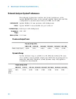
Страница 142: ...ng loads Temperature Range 25 C 5 C Warm up Time 0 5 hour Maximum Output Power Dynamic Range System dynamic range is calculated as the difference between the noise floor and the source maximum output power Reflection measurements are limited by directivity Therefore system dynamic range only applies to transmission measurements Frequency Range GHz 0 045 to 10 0 10 0 to 20 0 20 0 to 30 0 30 0 to 40...

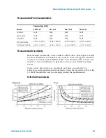
Страница 143: ...racy and residual systemic errors Curves show the worst case magnitude and phase uncertainty for reflection and transmission measurements using the specified cal kit with 10 Hz IF bandwidth and no averaging during the measurement Reflection Measurements Frequency Range GHz Residual 0 045 to 2 0 2 0 to 20 0 20 0 to 40 0 40 0 to 50 0 Directivity 42 dB 42 dB 38 dB 36 dB Source match 41 dB 38 dB 33 dB...

Страница 144: ...144 Installation and User s Guide G Network Analyzer Performance Specification Summary Transmission Measurements ...

Страница 145: ...ance with electrostatic discharge immunity test 9 EMC requirements 9 noise requirements 9 surge immunity test 9 compliance CSA 1010 8 compliance statement of 8 conformity declaration of 8 connections system 28 36 50 52 controller system overview 59 CPU requirements controller 59 crate shipment packing procedure 108 unpacking procedure 66 CSA 1010 compliance 8 customer support Agilent Technologies ...

Страница 146: ...quirements compliance with 9 O operating system requirements controller 59 output power maximum 142 P panels feedthrough 71 filler 72 parameter analyzer calibration cycle 117 functional verification procedure manual 121 GPIB address 56 parametric measurement solution calibration cycle 117 connections system 28 36 50 52 GPIB address 56 specifications 62 parts replaceable list of 69 ordering 106 pow...

Страница 147: ...arameter analyzer manual verification 121 U uncertainties measurement correcting 115 reflection 143 transmission 144 V verification functional description of choices 92 dynamic signal analyzer procedure manual 135 LCR meter 100 procedure manual 131 modeling system description 94 procedure remote 95 network analyzer description 124 130 134 procedure manual 125 parameter analyzer description 120 pro...

Страница 148: ...148 Installation and User s Guide Index ...

Отзывы: