


FINAL
TRIM
SIZE
:
7.5
in
x
9.0
in
Calibration
Overview
User
Calibrations
The
analyzer
calibrates
to
the
tip
of
the
probe
by
setting
the
probe
attenuation
to
the
actual
attenuation
ratio
of
the
probe
.
The
CAL
signal
is
internally
routed
to
the
probe
tip
for
Agilent
active
probes
.
The
mainframe's
CAL
signal
is
a
voltage
source
,
therefore
you
can
let
the
instrument
compensate
for
the
actual
characteristics
of
your
probe
by
letting
the
instrument
calibrate
to
the
tip
of
the
probe
.
The
instrument
automatically
calibrates
to
the
tip
of
the
probe
,
sets
the
probe
attenuation,
and
compensates
for
any
probe
oset.
If
you
do
not
perform
a
probe
calibration
but
want
to
use
a
passive
probe
,
enter
the
attenuation
factor
using
the
following
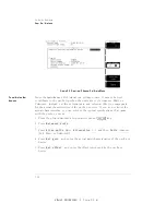
steps:
1.
Press
the
plug-in
module's
front-panel
channel
4
SETUP
5
key
.
2.
Press
NNNNNNNNNNNNNNNNNNNNNNNNNNNNNNNNNNNNNNNNNNNN
External
scale
and
then
NNNNNNNNNNNNNNNNNNNNNNNNNNNNNNNNNNN
Attenuation
.
Y
ou
can
use
the
probe
calibration
to
calibrate
any
network,
including
probes
or
cable
assemblies
.
The
instrument
calibrates
the
voltage
at
the
tip
of
the
probe
or
the
cable
input.
T
o
calibrate
an
Agilent
identiable
probe
1.
Press
the
plug-in
module's
front-panel-channel
4
SETUP
5
key
.
2.
Press
NNNNNNNNNNNNNNNNNNNNNNNNNNNNN
Calibrate
and
then
NNNNNNNNNNNNNNNNNNNNNNNNNNNNNNNNNNNNNNNNNNNNNNN
Calibrate
Probe
.
T
o
calibrate
a
non-identiable
probe
1.
Connect
the
voltage
probe
to
the
plug-in.
2.
Attach
the
probe
tip
to
the
CAL
hook
that
is
located
near
the
oppy
disk
drive
.
3.
Press
the
plug-in
module's
front-panel
channel
4
SETUP
5
key
.
4.
Press
N
NNNNNNNNNNNNNNNNNNNNNNNNNNNN
Calibrate
and
then
N
NNNNNNNNNNNNNNNNNNNNNNNNNNNNNNNNNNNNNNNNNNNNNN
Calibrate
probe
.
If
the
probe
being
calibrated
has
an
attenuation
factor
that
allows
the
instrument
to
adjust
the
gain
(in
hardware)
to
produce
even
steps
in
the
vertical
scale
factors
,
the
instrument
will
do
so
.
Typically
,
probes
have
standard
attenuation
factors
such
as
divide
by
10,
divide
by
20,
or
divide
by
100.
3-11
Содержание 54751A
Страница 1: ......
Страница 2: ...FINAL TRIM SIZE 7 5 in x 9 0 in User s Guide Agilent 83483A 4A 4B and 54751A 2A 2B Plug In Modules ...
Страница 8: ...FINAL TRIM SIZE 7 5 in x 9 0 in Declaration of Conformity vii ...
Страница 9: ...FINAL TRIM SIZE 7 5 in x 9 0 in viii ...
Страница 15: ...FINAL TRIM SIZE 7 5 in x 9 0 in Contents ...
Страница 16: ...FINAL TRIM SIZE 7 5 in x 9 0 in 1 The Instrument at a Glance ...
Страница 22: ......
Страница 25: ...FINAL TRIM SIZE 7 5 in x 9 0 in TheInstrumentata Glance ...
Страница 26: ...FINAL TRIM SIZE 7 5 in x 9 0 in 2 Channel Setup Menu ...
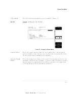
Страница 28: ...FINAL TRIM SIZE 7 5 in x 9 0 in ChannelSetupMenu Figure2 1 ElectricalChannel Setupmenu 2 3 ...
Страница 38: ...FINAL TRIM SIZE 7 5 in x 9 0 in 3 Calibration Overview ...
Страница 52: ...FINAL TRIM SIZE 7 5 in x 9 0 in 4 Speci cations and Characteristics ...
Страница 60: ......
Страница 67: ...FINAL TRIM SIZE 7 5 in x 9 0 in InCaseofDi culty ...
Страница 68: ...FINAL TRIM SIZE 7 5 in x 9 0 in Index ...
Страница 73: ...FINAL TRIM SIZE 7 5 in x 9 0 in ...


