6- 9
Replacing Assemblies
To remove the display
4
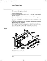
Use a flat-blade screwdriver to gently unhook the latch that holds the
white power-actuator shaft to the power switch, then disconnect the
shaft from the power switch. After you disconnect the shaft, make sure
you position it in the recess along the side of the display bracket.
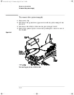
Figure 6-6
Unhooking the power switch shaft
5
Lift the display and remove it from the deck.
6
When reinserting the power shaft, push the shaft into the power switch
until the shaft seats.
(
Gently apply outward
pressure at this corner
of the slot
service.book Page 9 Wednesday, August 28, 2002 3:25 PM
Содержание 54641A
Страница 4: ...iv service book Page iv Wednesday August 28 2002 3 25 PM ...
Страница 7: ...1 General Information ...
Страница 24: ...1 18 ...
Страница 25: ...2 Preparing the Oscilloscope for Use service book Page 1 Wednesday August 28 2002 3 25 PM ...
Страница 45: ...3 Testing Performance service book Page 1 Wednesday August 28 2002 3 25 PM ...
Страница 66: ...3 22 service book Page 22 Wednesday August 28 2002 3 25 PM ...
Страница 67: ...4 Calibrating and Adjusting service book Page 1 Wednesday August 28 2002 3 25 PM ...
Страница 76: ...4 10 service book Page 10 Wednesday August 28 2002 3 25 PM ...
Страница 77: ...5 Troubleshooting service book Page 1 Wednesday August 28 2002 3 25 PM ...
Страница 90: ...5 14 service book Page 14 Wednesday August 28 2002 3 25 PM ...
Страница 91: ...6 Replacing Assemblies service book Page 1 Wednesday August 28 2002 3 25 PM ...
Страница 107: ...7 Replaceable Parts service book Page 1 Wednesday August 28 2002 3 25 PM ...
Страница 114: ...7 8 service book Page 8 Wednesday August 28 2002 3 25 PM ...


