


71
Chapter 5: Troubleshooting
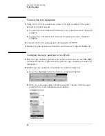
To Assemble the 2 x 9 Test Connectors
To Assemble the 2 x 9 Test Connectors
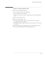
The 2 x 9 test connectors are used to connect all 16 channels and the clock of the
logic analyzer to the pulse generator so you can test the flying lead probe and
cables. (See “To test the cables” on page 73.)
Materials Required
Build two test connectors using SMA connectors and 2-by-9 sections of pin strip.
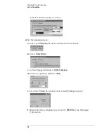
1
Prepare the pin strip header:
a
Cut or cleanly break two 2 x 9 sections from the pin strip.
b
Solder a jumper wire to all nine pins on one side of the pin strip.
c
Solder a jumper wire to all nine pins on the other side of the pin strip.
d
Solder two resistors to the pin strip, one at each end between the end
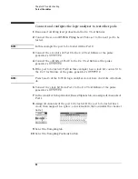
Material
Critical Specification
Recommended Model/Part
Pin Strip Header
(Qty 1, which will be separated)
.100" x .100" Pin Strip Header,
straight, pin length .230", two rows,
.120" solder tails, 2 x 40 contacts
3M 2380-6121TN or similar 2- row
with 0.1” pin spacing
Jumper wire
<6 inches, approximately 22 gauge
Resistor, 100 ohm 1%
(Qty 4)
SMA Board Mount Connector
(Qty 2)
Johnson 142-0701-801
(see www.johnsoncomponents.com)
Содержание 16900 Series
Страница 3: ...3 Chapter The 16910A Logic Analyzer The 16911A Logic Analyzer...
Страница 8: ...8 Contents...
Страница 14: ...14 Chapter 1 General Information...
Страница 15: ...15 2 Preparing for Use This chapter gives you instructions for preparing the logic analyzer module for use...
Страница 18: ...18 Chapter 2 Preparing for Use...
Страница 61: ...61 4 Calibrating This chapter gives you instructions for calibrating the logic analyzer...
Страница 63: ...63 5 Troubleshooting This chapter helps you troubleshoot the module to find defective assemblies...
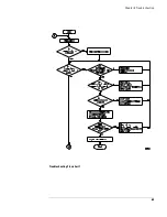
Страница 65: ...65 Chapter 5 Troubleshooting Troubleshooting Flowchart 1...
Страница 66: ...66 Chapter 5 Troubleshooting Troubleshooting Flowchart 2...
Страница 82: ...82 Chapter 5 Troubleshooting To test the cables 18 Return to the troubleshooting flow chart...
Страница 94: ...94 Chapter 7 Replaceable Parts 16910A Exploded View Exploded view of the 16910A logic analyzer...
Страница 95: ...95 Chapter 7 Replaceable Parts 16911A Exploded View Exploded view of the 16911A logic analyzer...
Страница 96: ...96 Chapter 7 Replaceable Parts...
Страница 97: ...97 8 Theory of Operation This chapter presents the theory of operation for the logic analyzer card...
Страница 102: ...102 Index...


