


28
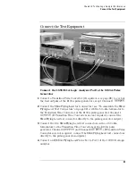
Chapter 3: Testing Logic Analyzer Performance
Equipment Required
Equipment Required
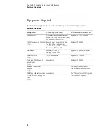
The following equipment is required for the performance test procedure.
Equipment Required
Equipment
Critical Specification
Recommended Model/Part
Pulse Generator
≥
260 MHz, two channels, differential
outputs, 150-180 ps rise/fall time (if faster,
use transition time converters)
Agilent or HP 8133A option 003
150 ps Transition Time Converter
(Qty 3)
Required if pulse generator’s rise time is
less than 150 ps. (Pulse generator
conditions: Voffset=1V,
∆
V=500 mV.)
Required for 8133A opt. 003.
Agilent or HP 15435A
Oscilloscope
bandwidth
≥
1.5 GHz,
sampling rate
≥
8 GSa/s
Agilent or HP 54845A/B or similar
SMA Coax Cable
(Qty 2)
>18 GHz bandwidth
Agilent or HP 8120-4948
Flying Lead Probe Set with 5
ground leads
(Qty 2)
no substitute
Agilent or HP E5383A
Male BNC to Female SMA
adapters
(Qty 2)
Cambridge Products CP-AD507
(see www.cambridgeproducts.com)
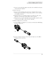
SMA/Flying Lead test connectors,
(f) SMA to (f) SMA to Flying Lead
Probe
(Qty 3)
no substitute
See “To Assemble the SMA/Flying Lead
Test Connectors” on page 22
Содержание 16900 Series
Страница 3: ...3 Chapter The 16910A Logic Analyzer The 16911A Logic Analyzer...
Страница 8: ...8 Contents...
Страница 14: ...14 Chapter 1 General Information...
Страница 15: ...15 2 Preparing for Use This chapter gives you instructions for preparing the logic analyzer module for use...
Страница 18: ...18 Chapter 2 Preparing for Use...
Страница 61: ...61 4 Calibrating This chapter gives you instructions for calibrating the logic analyzer...
Страница 63: ...63 5 Troubleshooting This chapter helps you troubleshoot the module to find defective assemblies...
Страница 65: ...65 Chapter 5 Troubleshooting Troubleshooting Flowchart 1...
Страница 66: ...66 Chapter 5 Troubleshooting Troubleshooting Flowchart 2...
Страница 82: ...82 Chapter 5 Troubleshooting To test the cables 18 Return to the troubleshooting flow chart...
Страница 94: ...94 Chapter 7 Replaceable Parts 16910A Exploded View Exploded view of the 16910A logic analyzer...
Страница 95: ...95 Chapter 7 Replaceable Parts 16911A Exploded View Exploded view of the 16911A logic analyzer...
Страница 96: ...96 Chapter 7 Replaceable Parts...
Страница 97: ...97 8 Theory of Operation This chapter presents the theory of operation for the logic analyzer card...
Страница 102: ...102 Index...


