


39
Chapter 3: Testing Logic Analyzer Performance
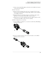
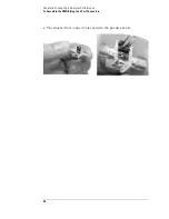
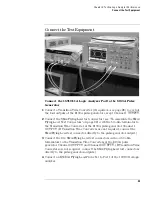
Connect the Test Equipment
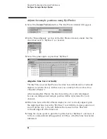
Set the 8133A pulse width
1
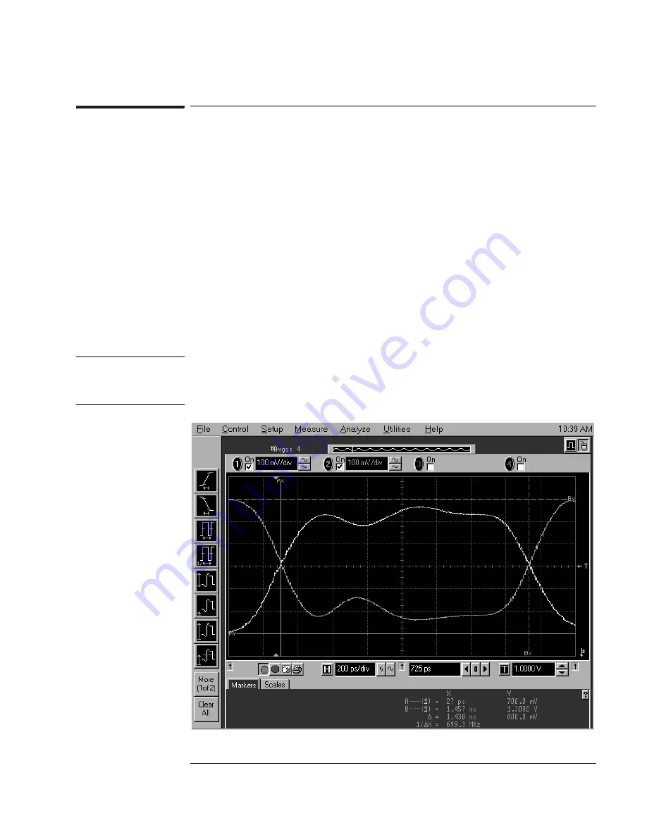
On the 8133A pulse generator, set the Channel 2 pulse width to 1.5 ns.
2
Observe the 54845A oscilloscope display. Change the Channel 2 pulse
width of the 8133A pulse generator so that the pulse width measured at 1
volt on the oscilloscope is equal to 1.5 ns minus the measurement
uncertainty and display resolution of the oscilloscope, further reduced by
35 ps for test margin.
If you are using the 54845A/B oscilloscope, the measurement uncertainty
is ±((0.007% *
∆
t) + (full scale/2x memory depth) + 30 ps) = ±30.10 ps.
Add 5 ps for display resolution. Add 35 ps test margin.
1.5 ns - 30.10 ps - 5 ps - 35 ps = 1.43 ns. Set the pulse width as measured
on the 54845A/B oscilloscope to 1.43 ns.
NOTE:
On the oscilloscope move the Ax and Bx markers to the crossing points of
the pulse and the horizontal center line. Read the pulse width at the
bottom of the screen. It is displayed as “
∆
=”.
Содержание 16900 Series
Страница 3: ...3 Chapter The 16910A Logic Analyzer The 16911A Logic Analyzer...
Страница 8: ...8 Contents...
Страница 14: ...14 Chapter 1 General Information...
Страница 15: ...15 2 Preparing for Use This chapter gives you instructions for preparing the logic analyzer module for use...
Страница 18: ...18 Chapter 2 Preparing for Use...
Страница 61: ...61 4 Calibrating This chapter gives you instructions for calibrating the logic analyzer...
Страница 63: ...63 5 Troubleshooting This chapter helps you troubleshoot the module to find defective assemblies...
Страница 65: ...65 Chapter 5 Troubleshooting Troubleshooting Flowchart 1...
Страница 66: ...66 Chapter 5 Troubleshooting Troubleshooting Flowchart 2...
Страница 82: ...82 Chapter 5 Troubleshooting To test the cables 18 Return to the troubleshooting flow chart...
Страница 94: ...94 Chapter 7 Replaceable Parts 16910A Exploded View Exploded view of the 16910A logic analyzer...
Страница 95: ...95 Chapter 7 Replaceable Parts 16911A Exploded View Exploded view of the 16911A logic analyzer...
Страница 96: ...96 Chapter 7 Replaceable Parts...
Страница 97: ...97 8 Theory of Operation This chapter presents the theory of operation for the logic analyzer card...
Страница 102: ...102 Index...


