


Page 34/79 – v2.9
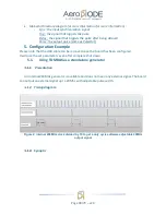
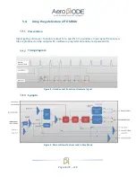
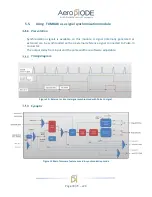
Timing diagram
Figure 4 : Delayed and pulse width adjusted signal from input to output
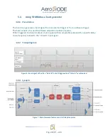
Synoptic
Figure 5 : Main firmware features used in Digital Delay Generator
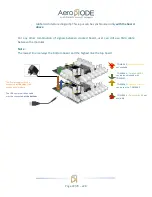
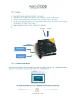
Cabling
1.
Plug the USB-Jack cable in the “
USB In”
connector
2.
Plug the signal generator (i.e. the signal you want to delay) in the “
Pulse In”
SMA
connector
3.
The software adjustable delay and pulse width signal will output on the “
Pulse Out
” SMA
connector
4.
Finally, plug the power supply to the “
Power In
” connector to power on the board
Содержание TOMBAK
Страница 19: ...Page 19 79 v2 9...