


Page 17/79 – v2.9
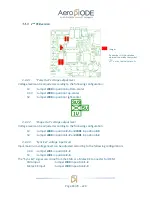
Jumper
Pin number 1 is indicated on
electronic board by the symbol
« » or by the indicator « 1 ».
4.4.1.1.
“Pulse Out” voltage output level
Voltage level can be adjusted according to the following configuration:
-
1V
: Jumper
J901
in position
2-3
-
3,3V : Jumper
J901
in position
1-2
and
J900
in position
1-2
-
TTL
: Jumper
J901
in position
1-2
and
J900
in position
2-3
4.4.1.2.
“Shape Out” voltage output level
Voltage level can be adjusted according to the following configuration:
-
1V
: Jumper
J800
in position
2-3
and
J801
in position
2-3
-
5V
: Jumper
J800
in position
1-2
and
J801
in position
1-2
4.4.1.3.
“Sync Ext” voltage input level
Input maximum voltage level can be adjusted according to the following configuration:
-
3.3V : Jumper
J301
in position
1-2
(mistake on the PCB label)
-
5V
: Jumper
J301
in position
2-3
(mistake on the PCB label)
The “Sync Ext” signal can come from the SMA or a Molex KK connector for OEM:
-
SMA input
: Jumper
J300
in position
1-2
(mistake on the PCB label for old PCB
version < 3.1 )
-
Molex KK input
: Jumper
J300
in position
2-3
(mistake on the PCB label for old PCB
version < 3.1 )
Содержание TOMBAK
Страница 19: ...Page 19 79 v2 9...


