background image

22.05 – 4037365_03

49

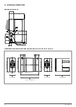
 NLC H 0280-1250 (P1-P2-P3-P4)


Water filter: Installation in the immediate vicinity of the heat exchanger is man-
datory,.

Components as standard

Plate heat exchanger

Water temperature sensors (IN/OUT)

Air drain valve

Pressure relief valve

Pump

Expansion vessel

Drain valve

Components not provided and responsibility of the installer

Flow shut-off valves

Air drain valve

10  Pressure relief valve
11  Expansion vessel
12  Storage tank
13  Water filter (MANDATORY)
14  Anti-vibration joints
15  Pressure gauge
16  Antifreeze electric heater
17  Drain valve
18  Flow switch (MANDATORY)

1

2

2

14

14

3

4

13

18

12

6

9

8

10

11

8

15

15

16

7

P1-P3

5

P2-P4

17

5

5

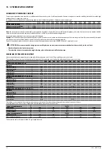
 Water  characteristics

System: Chiller with plate heat exchanger

PH

7,5 - 9

Total hardness

4,5 - 8,5 °dH

Temperature

< 65 °C

Oxygen content

< 0,1 ppm

Max. glycol amount

50 %

Phosphates (PO₄)

< 2ppm

Manganese (Mn)

< 0,05 ppm

Iron (Fe)

< 0,3 ppm

Alkalinity (HCO₃)

70 - 300 ppm

Chloride ions (Cl-)

< 50 ppm

Sulphate ions (SO₄)

< 50 ppm

Sulphide ion (S)

None

Ammonium ions (NH₄)

None

Silica (SiO₂)

< 30 ppm

It is of fundamental importance to keep the oxygen concentration in 

the water under control, especially in open vessel systems. This type 

of system, in fact, is very sensitive to the phenomenon of extra-oxy-

genation of the water (an event that can be encouraged by the incor-

rect positioning of some components). This phenomenon can trigger 

corrosion processes and subsequent drilling of the heat exchanger 

and pipes.

Содержание NLC 0280H

Страница 1: ...o n o f O r i g i n a l i n s t r u c t i o n s w w w a e r m e c c o m Installation Manual REVERSIBLE AIR WATER HEAT PUMP C o o l i n g c a p a c i t y 1 4 1 8 4 5 t o n H e a t i n g c a p a c i t y 1 6 3 8 7 5 9 7 3 9 5 5 B T U h NLC 0280H 1250H ...

Страница 2: ......

Страница 3: ...nt to present the product and help you select the unit that best meets the needs of your system However please note that for a more accurate selection you can also use the Magellano selection program available on our website Aermec Aermec always attentive to the continuous changes in the market and its regulations reserves the right to make all the changes deemed necessary for improving the produc...

Страница 4: ...hout the EU To prevent possible harm to the envi ronment or human health from uncontrolled disposal of Waste Electrical and Electronic Equipment WEEE please return the device using appropriate collection systems or contact the retailer where the product was purchased Please contact your local authority for further details Illegal dumping of the product by the user entails the application of admini...

Страница 5: ...tribution and centres of gravity during operation p 34 Antivibration p 35 11 Weights p 36 12 Dimensional tables p 37 0280 0300 0330 0350 00 p 37 0550 0600 0650 0675 00 p 38 0550 0600 0650 0675 P1 P2 P3 P4 p 39 0550 0600 0650 0675 01 02 03 04 p 40 0750 0800 0900 1000 1100 1250 00 p 41 13 Hydraulic connections p 42 0280 0300 0330 0350 00 p 42 Components supplied for sizes 0550 0600 0650 0675 00 P1 P...

Страница 6: ...6 22 05 4037365_03 23 Accessories p 58 Factory fitted accessories p 58 Accessories compatibility p 58 ...

Страница 7: ...ec shall not be held liable for the failure to observe the safety and accident prevention regulations in force Personal protective equipment PPE 1 Operations Handling Installation and or maintenance Welding or brazing Safety gloves helmet goggles safety footwear protective garments Earmuffs 1 It is recommended to follow the instructions in EN 378 3 Observe the laws in force in the country of unit ...

Страница 8: ...res on elec trical equipment and for lubricant oil of the compressor and the refrigerant The unit contains pressurised refrigerant gas no operation may be performed on pressurised equipment except during maintenance which must be per formed by skilled and qualified personnel Perform brazing or welding only on empty pipes and clear of any lubricating oil residues do not near flames or other heat so...

Страница 9: ... poses a serious risk The combined effects of the salt loaded mist and in dustrial emissions accelerate corrosion Within the manufacturing plants corrosive gas may result from the processing of chemicals or by the typical industrial processes used in manufacturing Potential sources of risk to be considered are open sewage systems exhaust vents diesel engine exhaust emissions from heavy traffic lan...

Страница 10: ...tilation Don t place or storage the refrigerating system in confined spaces Avoid traps where gases may fall and stagnate Avoid open flames and ignition sources near the refrigerant system INSTALLATION REQUIREMENTS In particular the unit is intended to be connected to a hydronic system that must be designed to be classified according to EN 378 1 as an indirect ventilated system ref EN 378 1 2016 p...

Страница 11: ...icularly windy locations the provision of wind barriers may be necessary to avoid malfunctions It should be installed if wind speed is above 4 9 knot POWER SUPPLY 460V 575V Operating range at the maximum outside air temperature in cooling mode 0280 0300 0330 0550 0600 0650 0750 0800 0900 1000 1100 1250 Key A External air temperature F B Water produced temperature F B A F F 0 0 14 0 114 8 40 0 60 0...

Страница 12: ...ey A External air temperature F B Water produced temperature F B A F F 0 0 14 0 114 8 40 0 60 0 80 0 100 0 105 5 120 0 30 0 39 2 50 0 60 0 70 0 44 0 64 4 0300 0330 0650 1100 1250 Key A External air temperature F B Water produced temperature F B A F F 0 0 14 0 107 5 40 0 60 0 80 0 100 0 98 2 120 0 30 0 39 2 50 0 60 0 70 0 44 0 64 4 ...

Страница 13: ...7 40 0 60 0 80 0 100 0 96 4 120 0 30 0 39 2 50 0 60 0 70 0 44 0 64 4 Operating heating mode range 0280 0300 0330 0350 0550 0600 0750 0800 0900 1000 Key A Water produced temperature F B External air temperature F F F 0 0 20 0 40 0 60 0 77 0 95 0 120 0 131 0 140 0 0 0 5 0 20 0 40 0 32 0 60 0 80 0 100 0 107 6 120 0 B A ...

Страница 14: ...0 0 0 5 0 20 0 42 8 32 0 60 0 80 0 100 0 107 6 120 0 B A POWER SUPPLY 230V Operating range at the maximum outside air temperature in cooling mode 0280 0300 0330 0550 0600 0650 0750 0800 0900 1000 1100 Key A External air temperature F B Water produced temperature F B A F F 0 0 14 0 114 8 40 0 60 0 80 0 100 0 105 5 120 0 30 0 39 2 50 0 60 0 70 0 44 0 64 4 ...

Страница 15: ...produced temperature F B A F F 0 0 14 0 113 0 40 0 60 0 80 0 100 0 103 7 120 0 30 0 39 2 50 0 60 0 70 0 44 0 64 4 0350 Key A External air temperature F B Water produced temperature F B A F F 0 0 14 0 111 2 40 0 60 0 80 0 100 0 101 9 120 0 30 0 39 2 50 0 60 0 70 0 44 0 64 4 ...

Страница 16: ...l air temperature F B Water produced temperature F B A F F 0 0 14 0 114 8 40 0 60 0 80 0 100 0 105 5 120 0 30 0 39 2 50 0 60 0 70 0 44 0 64 4 0300 0330 0600 0650 0900 1000 1100 Key A External air temperature F B Water produced temperature F B A F F 0 0 14 0 107 5 40 0 60 0 80 0 100 0 98 2 120 0 30 0 39 2 50 0 60 0 70 0 44 0 64 4 ...

Страница 17: ...ter produced temperature F B A F F 0 0 14 0 105 7 40 0 60 0 80 0 100 0 96 4 120 0 30 0 39 2 50 0 60 0 70 0 44 0 64 4 0350 Key A External air temperature F B Water produced temperature F B A F F 0 0 14 0 40 0 60 0 80 0 103 9 94 6 120 0 30 0 39 2 50 0 60 0 70 0 44 0 64 4 ...

Страница 18: ...ure F B External air temperature F F F 0 0 20 0 40 0 60 0 77 0 95 0 120 0 131 0 140 0 0 0 5 0 20 0 40 0 32 0 60 0 80 0 100 0 107 6 120 0 B A 0650 0675 1100 1250 Key A Water produced temperature F B External air temperature F F F 0 0 20 0 40 0 60 0 77 0 95 0 122 0 127 4 140 0 0 0 5 0 20 0 42 8 32 0 60 0 80 0 100 0 107 6 120 0 B A ...

Страница 19: ... 0750 0800 0900 1000 Key A External air temperature F B Water produced temperature F B A F F 0 0 14 0 114 8 40 0 60 0 80 0 100 0 105 5 120 0 30 0 39 2 50 0 60 0 70 0 44 0 64 4 0350 Key A External air temperature F B Water produced temperature F B A F F 0 0 14 0 111 2 40 0 60 0 80 0 100 0 101 9 120 0 30 0 39 2 50 0 60 0 70 0 44 0 64 4 ...

Страница 20: ... produced temperature F B A F F 0 0 14 0 107 6 40 0 60 0 80 0 100 0 98 3 120 0 30 0 39 2 50 0 60 0 70 0 44 0 64 4 0675 1250 Key A External air temperature F B Water produced temperature F B A F F 0 0 14 0 40 0 60 0 80 0 104 0 94 7 120 0 30 0 39 2 50 0 60 0 70 0 44 0 64 4 ...

Страница 21: ...ternal air temperature F B Water produced temperature F B A F F 0 0 14 0 114 8 40 0 60 0 80 0 100 0 105 5 120 0 30 0 39 2 50 0 60 0 70 0 44 0 64 4 0300 0330 0600 0900 1000 Key A External air temperature F B Water produced temperature F B A F F 0 0 14 0 107 5 40 0 60 0 80 0 100 0 98 2 120 0 30 0 39 2 50 0 60 0 70 0 44 0 64 4 ...

Страница 22: ...r produced temperature F B A F F 0 0 14 0 40 0 60 0 80 0 103 9 94 6 120 0 30 0 39 2 50 0 60 0 70 0 44 0 64 4 0650 1100 Key A External air temperature F B Water produced temperature F B A F F 0 0 14 0 40 0 60 0 80 0 100 3 91 0 120 0 30 0 39 2 50 0 60 0 70 0 44 0 64 4 ...

Страница 23: ...0 0 60 0 80 0 96 7 87 4 120 0 30 0 39 2 50 0 60 0 70 0 44 0 64 4 Operating heating mode range 0280 0300 0330 0350 0550 0600 0750 0800 0900 1000 Key A Water produced temperature F B External air temperature F F F 0 0 20 0 40 0 60 0 77 0 95 0 120 0 131 0 140 0 0 0 5 0 20 0 40 0 32 0 60 0 80 0 100 0 107 6 120 0 B A ...

Страница 24: ...2 05 4037365_03 0650 0675 1100 1250 Key A Water produced temperature F B External air temperature F F F 0 0 20 0 40 0 60 0 77 0 95 0 122 0 127 4 140 0 0 0 5 0 20 0 42 8 32 0 60 0 80 0 100 0 107 6 120 0 B A ...

Страница 25: ...c thermostatic expansion valve 20 Plate heat exchanger 1 2 3 4 5 5 6 7 8 3 9 10 11 12 13 14 15 16 17 12 12 12 13 15 16 18 19 20 Heating mode range 1 Fan Plug fan 2 Liquid separator 3 Pressure relief valve 4 Low pressure transducer 5 Compressor 6 Discharge temperature sensor 7 High pressure switch 8 High pressure transducer 9 Reversing valve 10 Finned coil 11 Isolation valve 12 One way valve 13 Fil...

Страница 26: ...3 4 4 5 5 6 6 6 7 7 8 8 2 2 2 2 3 6 7 20 9 9 10 10 11 12 12 14 14 13 13 11 11 11 9 9 15 15 16 16 17 17 18 18 19 7 20 Heating mode range 1 Fan Plug fan 2 One way valve 3 Filter drier 4 Solenoid valve 5 Liquid receiver with indicator light 6 Sight glass 7 Solenoid by pass valve 8 Mechanic thermostatic valve 9 Pressure relief valve 10 Low pressure transducer 11 Compressor 12 Discharge temperature sen...

Страница 27: ...ate 3 Packaging label When the unit is positioned make sure that the rating plate is well visible as the information provided on it is essential for correct maintenance PACKAGING HANDLING AND REMOVAL Before carrying out the packaging removal or transport operations put on personal protective equipment and use devices and instruments suitable for the dimensions and weigh of the equipment All handli...

Страница 28: ...rely technical requirements as well as any local laws in force For unit installation it is important to perform the following preliminary prepara tion tasks The following must be avoided Locations with aggressive atmospheres Areas in which the unit s noise level could be amplified due to reverberations or resonance POSITIONING The units must They must be installed in an area that cannot be accesse...

Страница 29: ...pplied from the fan to the in stantaneous drop of pressure in the tube When the machine is started for the first time the installer should set from the control panel the number of revs of the fan capable of providing head equal to the total pressure drops of the piping The number of fan revs is generally less than the maximum number of revs the fan is capable of 0 10 The number of revs is set indi...

Страница 30: ...30 22 05 4037365_03 WARNING The weight of the piping must not be borne by the appliance Example of ductwork ...

Страница 31: ... must have space to allow all routine and extraordinary maintenance to be performed C1 C2 B1 B2 A1 Size 0280 0300 0330 0350 0550 0600 0650 0675 0750 0800 0900 1000 1100 1250 Minimumtechnicalspaces A1 A in 39 4 39 4 39 4 39 4 39 4 39 4 39 4 39 4 39 4 39 4 39 4 39 4 39 4 39 4 B1 A in 39 4 39 4 39 4 39 4 39 4 39 4 39 4 39 4 39 4 39 4 39 4 39 4 39 4 39 4 B2 A in 19 7 19 7 19 7 19 7 19 7 19 7 19 7 19 7...

Страница 32: ... POSITION OF THE VIBRATION DAMPERS X Y G 1 2 3 4 1 2 3 4 XG Y G 1 2 3 4 5 6 XG Y G 1 2 3 4 XG Y G 1 2 3 4 5 6 XG Y G NLC 0280 0350 HA NLC 0550 0675 HA Vers 00 Vers P1 P4 Vers 00 P1 P4 Vers 01 04 Vers 01 04 Top view Top view ...

Страница 33: ... Centreofgravity empty X A in 70 2 68 3 67 6 67 3 71 3 68 1 67 6 66 3 133 9 132 8 134 0 129 8 130 2 128 7 Y A in 18 8 18 5 18 7 18 7 21 5 21 1 20 9 20 8 22 1 22 5 22 2 21 9 21 7 21 6 Weightdistributionin onthesupports empty 1 A 19 20 20 20 20 21 21 22 12 13 12 13 13 13 2 A 14 15 15 15 21 23 23 24 12 12 11 13 13 13 3 A 13 13 13 13 28 27 27 26 12 12 11 11 10 10 4 A 10 10 10 10 29 28 28 28 11 11 10 1...

Страница 34: ...280 0300 0330 0350 0550 0600 0650 0675 0750 0800 0900 1000 1100 1250 INTEGRATED HYDRONIC KIT 00 Centreofgravity duringoperation X A in 33 6 33 1 33 0 33 0 55 0 52 7 52 4 51 3 116 8 116 2 118 0 114 1 114 0 112 9 Y A in 16 2 15 8 16 3 16 2 20 9 20 4 20 3 20 2 21 6 22 0 21 8 21 6 21 3 21 2 Weightdistributionin onthesupports duringoperation 1 A 27 27 27 27 28 28 28 29 13 14 13 14 14 14 2 A 25 26 26 26...

Страница 35: ...3 121 0 Y A in 17 0 16 7 17 0 17 0 20 9 20 5 20 3 20 2 21 6 22 0 21 8 21 5 21 3 21 2 Weightdistributionin onthesupports duringoperation 1 A 29 29 30 30 26 26 26 27 13 13 12 14 13 14 2 A 26 27 27 27 28 29 30 30 13 13 12 14 14 14 3 A 24 23 23 23 23 21 21 20 11 11 10 10 9 9 4 A 21 21 21 21 24 23 24 23 11 11 10 10 9 9 5 A 15 15 17 16 16 16 6 A 15 14 16 16 16 16 7 A 12 12 11 11 12 11 8 A 12 11 11 11 12...

Страница 36: ... 639 7 961 8 263 8 574 8 783 INTEGRATED HYDRONIC KIT 02 04 Weights Emptyweight A lbs 2 542 2 646 2 694 2 714 3 765 4 065 4 231 4 336 6 365 6 552 6 892 7 189 7 566 7 776 Weightfunctioning A lbs 3 265 3 373 3 422 3 444 4 938 5 240 5 410 5 514 7 568 7 756 8 100 8 402 8 785 8 995 INTEGRATED HYDRONIC KIT P1 P3 Weights Emptyweight A lbs 2 037 2 141 2 189 2 209 3 179 3 479 3 622 3 728 5 595 5 796 6 133 6...

Страница 37: ...rge 11 9 3 0 10 1 1 2 29 6 11 8 2 0 1 6 2 0 2 0 11 8 1 6 4 9 40 2 43 3 A B C Size 0280 0300 0330 0350 INTEGRATED HYDRONIC KIT 00 01 02 03 04 P1 P2 P3 P4 Dimensionsandweightsfortransport A A in Contactthe factory Contactthe factory Contactthe factory Contactthe factory B A in Contactthe factory Contactthe factory Contactthe factory Contactthe factory C A in Contactthe factory Contactthe factory Con...

Страница 38: ... 3 Power supply 86 6 29 6 11 9 2 0 44 2 43 3 26 7 30 2 30 0 26 7 26 7 26 7 A B C Size 0550 0600 0650 0675 INTEGRATED HYDRONIC KIT 00 01 02 03 04 P1 P2 P3 P4 Dimensionsandweightsfortransport A A in 93 4 93 4 93 4 93 4 B A in 62 2 62 2 62 2 62 2 C A in 137 6 137 6 137 6 137 6 For the sizes shown in the table the transportation dimensions refer to the acces sory CRATE 22 ...

Страница 39: ... 15 8 15 8 124 1 44 2 43 3 92 6 0 7 43 3 Power supply A B C Size 0550 0600 0650 0675 INTEGRATED HYDRONIC KIT 00 01 02 03 04 P1 P2 P3 P4 Dimensionsandweightsfortransport A A in 93 4 93 4 93 4 93 4 B A in 62 2 62 2 62 2 62 2 C A in 137 6 137 6 137 6 137 6 For the sizes shown in the table the transportation dimensions refer to the acces sory CRATE 22 ...

Страница 40: ...6 1 6 3 5 3 4 26 7 26 7 26 7 26 7 42 8 1 9 1 9 6 8 26 7 26 7 6 8 124 1 1 9 1 9 26 7 26 7 3 4 A B C Size 0550 0600 0650 0675 INTEGRATED HYDRONIC KIT 00 01 02 03 04 P1 P2 P3 P4 Dimensionsandweightsfortransport A A in 93 4 93 4 93 4 93 4 B A in 62 2 62 2 62 2 62 2 C A in 137 6 137 6 137 6 137 6 For the sizes shown in the table the transportation dimensions refer to the acces sory CRATE 22 ...

Страница 41: ... 2 31 5 92 6 15 8 3 5 2 0 11 9 71 9 1 9 1 9 1 9 1 9 A B C Size 0750 0800 0900 1000 1100 1250 INTEGRATED HYDRONIC KIT 00 01 02 03 04 P1 P2 P3 P4 Dimensionsandweightsfortransport A A in Contactthe factory Contactthe factory Contactthe factory Contactthe factory Contactthe factory Contactthe factory B A in Contactthe factory Contactthe factory Contactthe factory Contactthe factory Contactthe factory ...

Страница 42: ...ved joints Ø 2 Desuperheater grooved joints Ø 1 1 2 COMPONENTS SUPPLIED FOR SIZES 0550 0600 0650 0675 00 P1 P2 P3 P4 01 02 03 04 Ø 76 1 mm Ø 2 1 2 EU Ø 76 1 mm Ø 2 1 2 EU Ø 73 mm Ø 2 1 2 US Ø 73 mm Ø 2 1 2 US 3 9 0 6 0 6 0 3 0 1 0 1 0 3 Grooved joint EU Grooved joint US Grooved nipple US Reduction adapter EU US ...

Страница 43: ...9 8 6 5 14 9 Evaporator grooved joints Ø 2 1 2 EU Pump grooved joints Ø 2 1 2 EU Desuperheater grooved joints Ø 1 1 2 0550 0600 0650 0675 01 02 03 04 5 6 11 9 3 1 5 6 2 0 11 9 85 7 71 9 9 5 24 1 49 8 6 5 2 0 Evaporator grooved joints Ø 2 1 2 EU Storage tank grooved joints Ø 2 1 2 EU Desuperheater grooved joints Ø 1 1 2 0750 0800 0900 1000 1100 1250 00 5 6 6 5 49 8 24 1 9 5 3 1 5 6 Evaporator groov...

Страница 44: ...e online at www aermec com It is important to follow the recommendations not complete below The water pipes must not transmit radial or axial forces or vibrations to the ex changers use flexible hoses to reduce the transmitted vibrations It is necessary to install manual or automatic vent valves in the highest points of the circuit and also provide discharge fittings in the lowest points to allow ...

Страница 45: ...inimum temperature provided for a given installation Take the necessary precautions if using non passivated anti freeze solu tions monoethylene glycol or monopropylene glycol Corrosion phenom ena may occur with these anti freeze solutions in contact with oxygen However always refer to the glycol supplier documentation to check its recom mended concentration IT IS FORBIDDEN to insert glycol in the ...

Страница 46: ...the winter period for heat pumps MAXIMUM SYSTEM WATER CONTENT Units with the hydronic kit mounted come standard with the expansion vessel set at 21 8 psi and the pressure relief valve The maximum system water content depends on the capacity of the expansion vessel and on the calibration of the pressure relief valve Size 0280 0300 0330 0350 0550 0600 0650 0675 0750 0800 0900 1000 1100 1250 INTEGRAT...

Страница 47: ... figure according to the formula p rating bar H ft 33 5 1 0 For example if level difference H is equal to 65 6 ft the calibration value of the vessel will be 33 4 psi If the calibration value obtained from the formula is less than 21 8 psi i e for H 40 2 use the standard calibration Key A Expansion vessel 1 Check that highest installation is not higher than 180 4 ft 2 Ensure that lowest utility ca...

Страница 48: ...ut off valves 1 2 2 9 9 16 3 5 7 6 8 11 13 15 12 5 10 10 14 4 Water characteristics System Chiller with plate heat exchanger PH 7 5 9 Total hardness 4 5 8 5 dH Temperature 65 C Oxygen content 0 1 ppm Max glycol amount 50 Phosphates PO 2ppm Manganese Mn 0 05 ppm Iron Fe 0 3 ppm Alkalinity HCO 70 300 ppm Chloride ions Cl 50 ppm Sulphate ions SO 50 ppm Sulphide ion S None Ammonium ions NH None Silica...

Страница 49: ...4 13 18 12 6 9 8 10 11 8 15 15 16 7 P1 P3 5 P2 P4 17 5 5 Water characteristics System Chiller with plate heat exchanger PH 7 5 9 Total hardness 4 5 8 5 dH Temperature 65 C Oxygen content 0 1 ppm Max glycol amount 50 Phosphates PO 2ppm Manganese Mn 0 05 ppm Iron Fe 0 3 ppm Alkalinity HCO 70 300 ppm Chloride ions Cl 50 ppm Sulphate ions SO 50 ppm Sulphide ion S None Ammonium ions NH None Silica SiO ...

Страница 50: ... P4 9 5 5 Water characteristics System Chiller with plate heat exchanger PH 7 5 9 Total hardness 4 5 8 5 dH Temperature 65 C Oxygen content 0 1 ppm Max glycol amount 50 Phosphates PO 2ppm Manganese Mn 0 05 ppm Iron Fe 0 3 ppm Alkalinity HCO 70 300 ppm Chloride ions Cl 50 ppm Sulphate ions SO 50 ppm Sulphide ion S None Ammonium ions NH None Silica SiO 30 ppm It is of fundamental importance to keep ...

Страница 51: ... design electric installations following international regulations and the national regulations of the country in which the unit is installed in compliance with the legislative regulations in force at the moment of installation it is mandatory to check the machine sealing before connecting the electrical wiring The machine must only be powered once the hydraulic and electric op erations are comple...

Страница 52: ... for the electric connection and always refer exclusively to the wiring diagram supplied with the unit Remove any protections from the cable fixing points For the functional connection of the unit take the power supply cable to the electric control board inside the unit and connect it to clamps L1 L2 L3 and PE respecting the polarities L1 L2 L3 as phases and PE as grounding Ensure that all protect...

Страница 53: ...talled in each inlet heat exchanger Mandatory component for warranty to be valid Check that the circulation pump s are working and that the wa ter flow rate is sufficient to close the flow switch contact if installed We recommend installing one always upstream of every heat exchanger Check the water flow rate measuring the pressure difference between inlet and outlet of the evaporator and calculat...

Страница 54: ... stop and take appropriate precautions to prevent their activation before accessing them If the unit has components such as integrated inverters disconnect the power supply and wait at least 15 minutes before accessing it for maintenance opera tions the internal components remain energised for this period generating the risk of electrocution Isolate the unit from the mains by means of the external...

Страница 55: ...e compressor inputs and outputs ther mometers connected to thermocouple probes that are fastened to the pipes at the compressor inputs and outputs Do not use metratasts as they require the operator to approach the machine s cooling circuit Turn on the machine and acquire the measurements remaining at a distance and in a position not exposed to the pressurised parts of the cooling circuit As soon a...

Страница 56: ...clean the coils refer to the dedicated chapter INTERVENTIONS ON THE CIRCUIT DESCRIPTION FREQUENCY Note 3Mths 6Mths 12Mths INTERVENTIONSONTHECOOLINGCIRCUITOPERATINGWITHFULLLOAD Measurementoftheoverheatingtemperature Measurementoftheundercoolingtemperature Measurementoftheexhaustgastemperature Measurementoffaninput Measurementofcompressorinput COMPRESSORCONTROLS Oillevelcontrol Oilaciditycontrol Con...

Страница 57: ... 3 60Hz with magnet circuit breakers 7 460V 3 60Hz with magnet circuit breakers 8 575V 3 60Hz with magnet circuit breakers 9 208V 3 60Hz with magnet circuit breakers 15 16 Integrated hydronic kit 00 Without hydronic kit Kitwithstoragetankandpump s 01 Storage tank with low head pump 02 Storage tank with low head pump stand by pump 03 Storage tank with high head pump 04 Storage tank with high head p...

Страница 58: ...el Ver 0280 0300 0330 0350 0550 0600 0650 0675 0750 0800 0900 1000 1100 1250 AER485P1 A AERBACP A AERNET A FL UL 1 A MULTICHILLER_EVO A PGD1 A 1 Compliant with UL regulation Special crate for transport Ver 0280 0300 0330 0350 0550 0600 0650 0675 0750 0800 0900 1000 1100 1250 Integratedhydronickit 00 P1 P2 P3 P4 A CRATE22 CRATE22 CRATE22 CRATE22 The accessory cannot be fitted on the configurations ...

Страница 59: ...background indicates the accessory must be assembled in the factory Ver 0675 0750 0800 0900 1000 1100 1250 A RIF 1 RIF 1 RIF 1 RIF 1 RIF 1 RIF 1 RIF 1 1 Contact the factory A grey background indicates the accessory must be assembled in the factory Electric heater kit for the base Ver 0280 0300 0330 0350 0550 0600 0650 0675 0750 0800 0900 1000 1100 1250 Powersupply 6 A KRB31 KRB31 KRB31 KRB31 KRB32...

Страница 60: ... e v i l a c q u a V R I t a l y P h o n e 3 9 0 4 4 2 6 3 3 1 1 1 F a x 3 9 0 4 4 2 9 3 5 7 7 s a l e s a e r m e c c o m w w w a e r m e c c o m 2 2 0 5 4 0 3 7 3 6 5 _ 0 3 4037365_03 DOWNLOAD THE LATEST VERSION http www aermec com qrcode asp q 4775 ...

Отзывы: