22.05 – 4037360_01
55
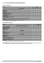
22 CONFIGURATOR
Field
Description
1,2,3
NLC
4,5,6,7
Size
0280, 0300, 0330, 0350, 0550, 0600, 0650, 0675, 0750, 0800, 0900, 1000,
1100, 1250
8
Operating field
° Standard mechanic thermostatic valve (1)
X Electronic thermostatic expansion valve (1)
Y Low temperature mechanic thermostatic valve (2)
Z Mechanic thermostatic valve (3)
9
Model
° Cooling only
10
Heat recovery
° Without heat recovery
D With desuperheater (4)
T With total recovery (5)
11
Version
A High efficiency
12
Coils
° Copper-aluminium
R Copper pipes-copper fins
S Copper pipes-Tinned copper fins
V Copper pieps-Coated aluminium fins
13
Fans
J Inverter
14
Power supply
6 230V ~ 3 60Hz with magnet circuit breakers
7 460V ~ 3 60Hz with magnet circuit breakers
8 575V ~ 3 60Hz with magnet circuit breakers
9 208V ~ 3 60Hz with magnet circuit breakers
15,16
Integrated hydronic kit
00 Without hydronic kit
Kit with storage tank and pump/s
01 Storage tank with low head pump
02 Storage tank with low head pump + stand-by pump
03 Storage tank with high head pump
04 Storage tank with high head pump + stand-by pump
Kit with pump/s
P1 Single pump low head
P2 Pump low head + stand-by pump
P3 Single pump high head
P4 Pump high head + stand-by pump
(1) Water produced up to 39.2 °F.
(2) Water produced from 32 °F up to 17.6 °F
(3) Water produced from 39.2 °F up to 32 °F
(4) When functioning, the temperature of the water in the heat exchanger inlet must never drop below 95°F. For
“YD” and “ZD” recovery versions, contact the headquarters.
(5) With this option the "Y" and "Z" valvs are not compatible. The units with total recovery are not configurable
with the integrated hydronic kit.
Содержание NLC 0280
Страница 2: ......
Страница 27: ...22 05 4037360_01 27 WARNING The weight of the piping must not be borne by the appliance Example of ductwork ...
Страница 58: ......
Страница 59: ......


