22.05 – 4037360_01
49
17 ELECTRICAL WIRING
For the installation requirements refer only to the wiring diagram
supplied with the unit. The wiring diagram along with the manuals
must be kept in good condition and always available for any future
servicing on the unit.
THE CABLE GLANDS ARE NOT SUPPLIED WITH THE UNIT
This equipment is compliant with IEC 61000-3-12 provided that the short circuit
power S
sc
is greater than or equal to R
sce
x S
equ
in the point of interface between the
user's power supply and the public network.
The equipment installer or user is responsible for making sure, together with the
distribution network operator if necessary, that the equipment is connected only
to a power supply with a short-circuit power S
sc
that is higher than or equal to R
sce
x S
equ
.
with:
— S
equ
= 400 [V] x 1.73 x I_rated [A]
— I_rated = machine input current under rated conditions [A]
— R
sce
= Machine "short circuit ratio".
The units are completely wired at the factory and only require connection to the
electric power supply mains, downstream from a unit switch, according to that
envisioned by the Standards in force on this subject in the country of installation.
It s also advised to check that:
— The electrical mains features are suitable for the absorption values indicated
in the electrical data table, also taking into consideration any other machines
functioning at the same time;
— The unit is only powered when installation has been completed (hydraulic and
electric);
— Respect the connection indications of the phase, and earth wires;
— The power supply line must have a relevant protection mounted upstream
against short circuits and dispersions to earth, which isolates the system with
respect to other utilities;
— The voltage must be within a tolerance of ± 10% of the nominal power supply
voltage of the machine (for unbalanced three-phase unit max 3% between the
phases). If these parameters are not respected, contact the energy supplier;
— For electric connections, use the cables with double isolation according to the
Standards in force on this subject in the different countries.
The following is mandatory
— The use of an omnipolar magnet circuit breaker switch, in compliance with the
current Standards (contact opening at least 0.1 in), with suitable cut-off power
and differential protection on the basis of the electric data table shown below,
installed as near as possible to the appliance;
— To make an effective earth connection. The manufacturer cannot be considered
responsible for any damage caused by the lack of or ineffective appliance earth
connection;
— For units with three-phase power supply, check the correct connection of the
phases.
All electrical operations:
must be carried out by personnel who fulfil the
necessary legal requirements and who have been trained and informed on
the risks correlated with those operations.
— The characteristics of the electrical lines and related components must be es-
tablished by personnel authorised to design electric installations, following
international regulations and the national regulations of the country in which
the unit is installed, in compliance with the legislative regulations in force at the
moment of installation;
— it is mandatory to check the machine sealing before connecting the electrical
wiring. The machine must only be powered once the hydraulic and electric op-
erations are completed;
— Electrical connections must be placed through the prepared sections (see figure
.X) using suitable cable glands with a minimum IP67 grade o higher;
— If the supply cord is damaged, it must be replaced by the manufacturer or its
service agent or a similarly qualified person in order to avoid a hazard.
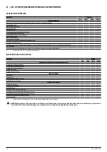
ELECTRIC DATA
Size
0280
0300
0330
0350
0550
0600
0650
0675
0750
0800
0900
1000
1100
1250
POWER SUPPLY: 6
Electric data
Peak current (LRA)
A
A
240.3
298.7
359.7
371.0
444.6
618.8
718.8
738.7
569.0
618.6
792.8
811.2
931.1
970.8
Minimum circuit amperage (MCA)
A
A
79.6
92.6
115.0
133.0
160.7
201.5
215.7
227.0
280.8
307.4
348.2
384.5
410.0
432.7
Maximum overcurrent permitted by the protection device (MOP)
A
A
107.2
125.9
166.3
184.3
216.5
275.4
300.9
312.3
336.6
363.2
422.1
458.4
495.3
518.0
POWER SUPPLY: 7
Electric data
Peak current (LRA)
A
A
127.7
157.4
182.4
187.5
235.6
285.8
332.8
341.8
294.5
320.2
370.4
378.7
434.7
452.7
Minimum circuit amperage (MCA)
A
A
42.2
53.8
59.4
63.9
84.4
93.7
108.1
119.6
139.8
158.7
168.0
176.4
202.2
225.1
Maximum overcurrent permitted by the protection device (MOP)
A
A
55.0
71.7
81.8
86.3
110.6
124.2
150.0
161.5
166.1
185.0
198.5
206.8
244.1
267.1
POWER SUPPLY: 8
Electric data
Peak current (LRA)
A
A
99.7
105.4
134.4
138.3
176.4
227.6
285.6
292.5
222.0
242.1
293.3
299.7
364.7
378.5
Minimum circuit amperage (MCA)
A
A
32.3
39.5
48.4
55.4
73.5
75.6
88.2
98.4
121.7
138.4
140.4
142.2
165.0
185.2
Maximum overcurrent permitted by the protection device (MOP)
A
A
41.9
52.4
68.2
75.3
97.3
100.2
123.0
133.1
145.4
162.1
165.0
166.8
199.7
220.0
POWER SUPPLY: 9
Electric data
Peak current (LRA)
A
A
248.5
307.9
368.9
381.5
458.2
633.4
733.4
746.3
592.5
645.5
820.6
841.0
953.9
979.8
Minimum circuit amperage (MCA)
A
A
84.4
97.4
119.8
137.8
166.9
207.7
221.9
233.3
285.7
312.2
353.0
389.3
414.9
437.5
Maximum overcurrent permitted by the protection device (MOP)
A
A
112.0
130.7
171.1
189.1
222.7
281.7
307.2
318.5
341.4
368.0
427.0
463.2
500.1
522.8
SINGLE HYDRONIC KITS’ ELECTRIC DATA
Size
0280
0300
0330
0350
0550
0600
0650
0675
0750
0800
0900
1000
1100
1250
Pumps
Maximum input power
00
kW
/
/
/
/
/
/
/
/
/
/
/
/
/
/
01,P1
kW
1.55
1.55
1.55
2.39
2.39
2.39
2.94
2.94
2.94
2.94
4.29
4.29
6.19
6.19
02,P2
kW
1.47
1.47
1.47
2.32
2.32
2.32
3.07
3.07
3.07
3.07
4.46
4.46
5.44
5.44
03,P3
kW
2.39
2.39
2.39
3.25
3.25
3.25
4.29
4.29
4.29
4.29
5.99
5.99
8.25
8.25
04,P4
kW
2.32
2.32
2.32
3.31
3.31
3.31
4.46
4.46
4.46
4.46
6.15
6.15
7.36
7.36
Maximum current
00
A
/
/
/
/
/
/
/
/
/
/
/
/
/
/
01,P1
A
2.80
2.80
2.80
4.00
4.00
4.00
5.50
5.50
5.50
5.50
6.70
6.70
8.90
8.90
02,P2
A
3.19
3.19
3.19
4.58
4.58
4.58
6.23
6.23
6.23
6.23
7.62
7.62
10.40
10.40
03,P3
A
4.00
4.00
4.00
5.50
5.50
5.50
6.70
6.70
6.70
6.70
8.90
8.90
12.20
12.20
04,P4
A
4.58
4.58
4.58
6.23
6.23
6.23
7.62
7.62
7.62
7.62
10.40
10.40
14.20
14.20
Содержание NLC 0280
Страница 2: ......
Страница 27: ...22 05 4037360_01 27 WARNING The weight of the piping must not be borne by the appliance Example of ductwork ...
Страница 58: ......
Страница 59: ......


