23 / 76
D7481_A_NOT_INST_VTZ_SMART
EN
FR
■
Lors de la connexion de interrupteur principal à la
source d‘alimentation principale, l‘électricien doit as-
surer la protection contre la foudre ainsi que la conne-
xion equipotentielle de l‘unité de ventilation. L‘unité de
ventilation est alors déjà prête à fonctionner avec les
paramètres préréglés.
En option, d’autres raccords peuvent être nécessaires.
Dans ce cas ils devront être directement placés sur l’unité
de commande de l‘unité de ventilation. Dans ce but, des
presse-étoupes séparés pour les câblages des commandes
sont à disposition.
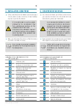
7.1. INSTALLATION DE LIAISON ÉQUIPOTENTIELLE
Danger!
Le fonctionnement de l‘unité de ven-
tilation sans installation correcte de
l‘équipotentialité est strictement inter-
dit. Cette violation peut entraîner des
blessures ou la mort par électrocution
même si l‘unité de ventilation est étein-
te. L‘installation, les essais et la main-
tenance de l‘égalisation potentielle doi-
vent être effectués par un électricien
qualifié autorisé sur site.
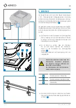
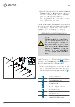
Toutes les unités de ventilation VTZ Smart et VTZ Smart Plus
sont équipées d‘une liaison équipotentielle
A
pour établir
l‘égalisation du potentiel au plénum associée DSF, DSFA ou
DSDSR.
■
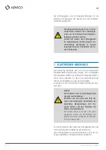
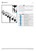
Si l‘unité de ventilation et le plénum sont fournis sépa-
rément, la liaison équipotentielle de l‘unité de ventila-
tion VTZ doit être raccordée au plénum comme indiqué
sur l‘image. (
4
)
1
Logement de douille
2
Vis à tête cylindrique M8
3
Rondelle
4
Courroie d‘égalisation potentielle
(courroie en cuivre)
5
Rondelle de contact M8
(contact sur le boîtier)
6
Écrou à sertir M8
7
Caisson de ventilation
■
Among the connection of the proximity switch to the
main power source the electrician has to ensure the
protection against lightening as well as the poten-
tial equalisation of the ventilation unit.
The ventilation unit is then immediately ready to opera-
te with the preset parameters.
Optionally, other connections may be necessary. When this
is the case, they must be placed directly on the control unit
of the ventilation unit. For this purpose, separate packing
boxes are available for the wiring of the controls.
7.1. INSTALATION OF EQUIPOTENTIAL BONDING
Danger!
Operation of the ventilation unit wit-
hout proper instalation of equipotential
bonding is strictly prohibited. Violations
can lead to injury or death by electro-
cution even if the ventilation unit is
turned off. The installation, testing and
maintenance of the potential equalista-
tion has to be performed by authorised
electrical skilled personal on site.
All ventilation units VTZ Smart and VTZ Smart Plus are
equipped with an equipotential bonding connection
A
to
establish potential equalisation to the associated base DSF,
DSFA or DSDSR.
■
If ventilation unit and base are suplied seperately, the
equipotential bonding connection of the ventilation unit
VTZ has to be connected to the base as shown in the
picture. (
4
)
1
Casing of base
2
Pan-head screw M8
3
Flat washer
4
Potential equalisation strap
(copper strap)
5
Contact disc M8 (contact on casing)
6
Rivet nut M8
7
Casing of ventilation unit
Содержание VTZ 0 Smart
Страница 73: ...73 76 D7481_A_NOT_INST_VTZ_SMART ...
Страница 74: ...74 76 D7481_A_NOT_INST_VTZ_SMART ...
Страница 75: ...75 76 D7481_A_NOT_INST_VTZ_SMART ...

