13 / 76
D7481_A_NOT_INST_VTZ_SMART
EN
FR
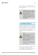
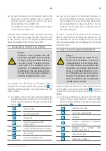
4. CONDITIONS DE MONTAGE
■
Les unités de ventilation pour terrasse et toit sont con-
çues pour être montées sur un socle dédié dont la sta-
bilité doit être garantie par l’installateur.
Il est recommandé d‘utilliser les socles
proposés par le fabricant, ces derniers
disposant des raccords préfabriqués
pour les unités de ventilation de la série.
Le constructeur de l’installation doit
veiller à ce que le raccord des condu-
its de ventilation au socle de l‘unité de
ventilation soit bien hermétique.
■
Suivre également les instructions du manuel d‘installa-
tion respectif du socle proposé par le fabricant.
Vérifier qu‘un espace libre d‘un mètre
minimum tout autour de l‘appareil est
disponible en cas d‘opération de main-
tenance.
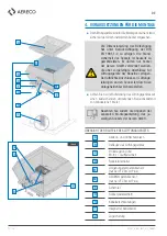
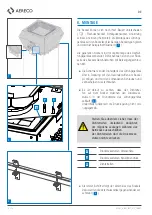
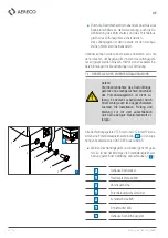
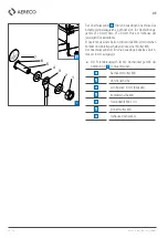
VUE D’ENSEMBLE DES COMPOSANTS DE
L‘UNITÉ DE VENTILATION
A
Grille de protection
B
Enveloppe de l‘unité de ventilation
C
Régulateur de pression et ensemble
moteur/ roto
D
Interrupteur principal
E1
Capteur de température ambiante
(VTZ Smart Plus seulement)
E2
Capteur de température d‘air extrait
(VTZ Smart Plus seulement)
F
Charnières
G
Socle de l‘unité de ventilation / adap-
teur (illustration à titre d‘exemple)
H
Presse-étoupes
I
Passage de câbles intégré
J
Système de blocage
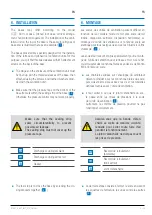
4. INSTALLATION CONDITIONS
■
Terrace and pitched roof ventilation units are designed
to be mounted on a base on the roof, of which stability
must be ensured by the installer.
It is recommended to use the adaptor
proposed by the manufacturer; they
have prefabricated junctions for the
ventilation units of the series.
The builder of the installation must see
to it that the junction of the ventilation
duct to the base of the ventilation unit
is perfectly airtight.
■
Make sure that around the unit is a sufficient clearance
for revision of at least one meter.
Also consider the separate installation
instructions for the respective base of
the manufacturer.
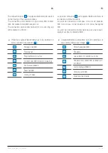
OVERVIEW OF THE COMPONENTS OF THE
VENTILATION UNIT
A
Protective grille
B
Enclosure of the ventilation unit
C
Pressure control device and
motor/rotor assembly
D
Proximity switch
E1
Surrounding temperature sensor
(only VTZ Smart Plus)
E2
Exhaust air temperature sensor
(only VTZ Smart Plus)
F
Hinges
G
Base / adaptor
(illustration as an example)
H
Packing box
I
Built-in cable grommets
J
Locking system
Содержание VTZ 0 Smart
Страница 73: ...73 76 D7481_A_NOT_INST_VTZ_SMART ...
Страница 74: ...74 76 D7481_A_NOT_INST_VTZ_SMART ...
Страница 75: ...75 76 D7481_A_NOT_INST_VTZ_SMART ...


