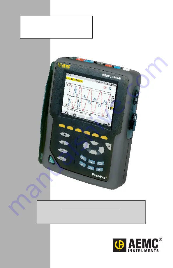
3-PHASE POWER QUALITY
ANALYZER
3945-B
PowerPad
®
E N G L I S H
User Manual
IMPORTANT WARRANTY NOTE:
By registering online within 30 days from the date of
purchase, your warranty will be extended to 3 years
Страница 1: ...3 PHASE POWER QUALITY ANALYZER 3945 B PowerPad E N G L I S H User Manual IMPORTANT WARRANTY NOTE By registering online within 30 days from the date of purchase your warranty will be extended to 3 year...
Страница 2: ......
Страница 3: ...o our repair and calibration facility for a nominal charge The recommended calibration interval for this instrument is 12 months and begins on the date of receipt by the customer For recalibration ple...
Страница 4: ...may take several hours In this case at least 5 charge discharge cycles will be necessary for your battery to recover 95 of its capacity To make the best possible use of your battery and extend its eff...
Страница 5: ...itions 17 3 2 Electrical Specifications 17 3 2 1 Voltage Inputs 17 3 2 2 Current Inputs 18 3 2 3 Accuracy Specifications excluding current probes 18 3 2 4 Nominal Range of Use 19 3 2 5 Power Supply 19...
Страница 6: ...41 5 1 3 RMS Current Measurement 42 5 1 4 Total Harmonic Distortion Measurement on One Phase 42 5 1 5 Minimum and Maximum Current Value Measurements 43 5 1 6 Simultaneous Display of Current Measuremen...
Страница 7: ...B to your Computer 69 6 3 Opening the Control Panel 70 6 4 Common Functions 72 6 5 Configuring the Instrument 72 6 5 1 Setup 73 6 5 2 Instrument Display 74 6 5 3 Alarm Conditions Configuration 75 6 5...
Страница 8: ...lues for Voltage and Current 93 Peak Factors for Current and Voltage 93 1 sec RMS Values for Voltage and Current 94 Voltage and Current Unbalance 94 THD Calculation 94 Calculation of Harmonic Bins 95...
Страница 9: ...tric shock The voltage at the parts marked with this symbol may be dangerous Refers to a type A current sensor This symbol signifies that application around and removal from HAZARDOUS LIVE conductors...
Страница 10: ...y of the battery indicator 1 4 Ordering Information PowerPad Model 3945 B Cat 2130 74 Includes extra large tool bag soft carrying pouch four 10 ft color coded voltage leads and alligator clips RS 232...
Страница 11: ...ur 10 ft color coded voltage leads and alligator clips RS 232 DB9F optically coupled serial cable RS 232 to USB adapter US 115V power cord rechargeable NiMH battery pack and a USB stick with DataView...
Страница 12: ...3 BK 5A 100A Cat 2140 36 MiniFlex Sensor 10 Model MA193 10 BK 1000A Cat 2140 48 Set of 4 Color coded 30 ft 9m Voltage Leads 600V CAT IV 10A Cat 2140 61 Replacement Lead Set of 4 Color coded 10 ft 3m w...
Страница 13: ...of DC voltage up to 850V Measurement of DC current up to 1400ADC with MR193 probe Frequency measurement 41 to 70Hz systems Calculation of neutral current for WYE configurations Calculation of Crest Fa...
Страница 14: ...ay with graphic representation of system parameters and measurements Six 6 function buttons used to modify the display mode Four 4 function buttons which allow the user to Access the instrument setup...
Страница 15: ...produced by non linear loads analysis of the problems caused by harmonics according to their order heating of neutrals conductors motors etc Waveforms View displays voltage and current waveforms or v...
Страница 16: ...S 0 300 t 5 0ms V1 276 V2 140 V3 145 3U 3V 3A L1 L2 L3 THD CF max min 5 2 1 3 4 202 5 v 202 0 v 202 7 v 1 2 3 07 25 02 49 99Hz 10 26 100 Figure 2 2 Top display bar indicates Symbol of the tested mode...
Страница 17: ...only be performed if voltage with a frequency of 41 to 70 Hz is applied to the Ch1 voltage input Selection of waveforms to be displayed use the buttons to select 3U displays the 3 phase to phase volt...
Страница 18: ...city level Battery sign and are fixed WARNING The battery may fully discharge when recording for long periods of time while not connected to a power supply The PowerPad will con tinue to record for so...
Страница 19: ...ements are maximum for Cos 1 or Sin 1 and are typical for the other phase shifts NOTE The symbol U will be used throughout this manual and in the instrument to refer to phase to phase voltage measurem...
Страница 20: ...rent App Apm 0 to 1 7 x Inom 0 1 A if I 1000 A 1 A if I 1000 A 1 1A Peak Current AmpFlex MiniFlex 10 to 9190A 0 1 A if I 1000 A 1 A if I 1000 A 1 1A Crest Factor Vcf Ucf Acf 1 00 to 9 99 0 01 1 2cts R...
Страница 21: ...values Vpm Upm and Apm Peak values min 3 2 4 Nominal Range of Use Frequency 40 to 69Hz Harmonics THD I 0 to 40 THD U 0 to 20 Magnetic field 40 0A m Earth s magnetic field Electrical field 3V m Relati...
Страница 22: ...de Operating 0 to 2000 meters 6560 ft Non Operating 0 to 10 000 meters 32800 ft Temperature and RH 0 10 45 75 90 95 122 95 79 68 4 32 Temperature in F Reference Range Operating Range Storage Range Rel...
Страница 23: ...DC current Magnetic field of external origin 40 A m earth s magnetic field Accuracy Primary current AAC 3 to 10A 10 to 100A 100 to 1200A Accuracy of the output signal 0 8 1ct 0 3 1ct 0 2 1ct Phase shi...
Страница 24: ...Distortion factor 1 no DC current Magnetic field of external origin 40 A m earth s magnetic field Accuracy Primary current AAC 2 to 10A 10 to 100A 100 to 240A Accuracy of the output signal 3 1ct 2 5 1...
Страница 25: ...obe Power calculations will also be zeroed when the current is zeroed Probe Output Signal 5A 200mV AAC 100A 10mV AAC Maximum Clamping Diameter 0 8 20mm Safety NF EN 61010 2 032 Pollution Degree 2 300V...
Страница 26: ...e direction of the load Nominal Range 3000AAC Measurement Range 10A to 6500AAC max Currents below 9A will be displayed as zero with this probe Probe Output Signal 140mVAC 3000AAC at 50Hz NOTE Output i...
Страница 27: ...included When installing probes face the arrow on the probe in the direction of the load Nominal Range 1000AAC Measurement Range 10A to 1000AAC max Currents below 10A will be displayed as zero with th...
Страница 28: ...be 3945 B accuracy included When installing probes face the arrow on the probe in the direction of the load Nominal Range 1000AAC 1400ADC max Measurement Range 10A to 1000AAC 10A to 1300APEAK AC DC Cu...
Страница 29: ...Relative humidity 10 to 90 RH 0 5 of Reading Battery voltage 6 5 to 10V 1 A V Position of a 20mm 20 conductor DC at 440Hz DC at 1Hz DC at 2Hz DC at 5Hz 0 5 of Reading 1 of Reading 3 of Reading 10 of...
Страница 30: ...urrent channel inputs It facilitates automatic sensor recognition and probe ratio programming for both 1A and 5A output probes Additionally the adapter box can be used directly in series in a 5 Amp ci...
Страница 31: ...ndary x 1000 will be displayed as zero on the PowerPad with this probe Range 5A Output Input Ratio 0 2mV mAAC Dimensions 6 00 x 3 74 x 3 38 153 x 95 x 86mm Weight 1 98 lbs 900g Impermeability IP50 per...
Страница 32: ...he same probe type for each phase When changing type of probe restart the 3945 B or select the correct probe type using the set up mode When installing probes face the arrow on the probe in the direct...
Страница 33: ...hen press the button Select the number to be modified with the buttons it will appear in bold type Modify the value of the number selected with the buttons Press the button to apply the new settings T...
Страница 34: ...ase current 3 Neutral current 07 25 02 10 26 100 Figure 4 2 Choose the phase with the buttons and the color for that phase with the buttons Press the button to apply the new settings 4 1 4 Calculation...
Страница 35: ...displayed but not valid On WYE network The neutral current is not calculated It is necessary to connect neutral V to obtain the power per phase 3 phase 4 wire connection 4V 3A The neutral current is a...
Страница 36: ...ucer ratio moves the cursor left or right to select which digit will be edited increases or decreases the value at the highlighted position Secondary current value Nominal value of primary current fro...
Страница 37: ...ce again be displayed on the screen In addition to the 4 current probe choices there is an adapter selection This selection allows the operator to use current probes that have a current output with Po...
Страница 38: ...lled There are two user defined parameters at the bottom of the window At first they will be listed as a question mark These parameters allow you to moni tor specific or a range of voltage current or...
Страница 39: ...for long periods of time while not connected to a power supply The PowerPad will continue to record for some time even if below the minimum battery charge value However the display may not come back o...
Страница 40: ...Tan Vh Uh Ah and VAh Threshold value for triggering an alarm Minimum duration from beginning threshold detection to store the alarm from 0 01 seconds to 99 minutes Less than or greater than Capture 3...
Страница 41: ...napshots captured tran sient states and all recordings are deleted The configuration will return to the default setting and the instrument will automatically turn OFF once the data has been deleted 4...
Страница 42: ...Voltage Measurement on a Three phase System 300V RMS 0 300 t 5 0ms V1 276 V2 140 V3 145 3U 3V 3A L1 L2 L3 THD CF max min 4 1 2 3 202 5 v 202 0 v 202 7 v 1 2 3 07 25 02 49 99Hz 10 26 100 Figure 5 1 Va...
Страница 43: ...stem The neutral current is not a direct measurement but the resulting total of the 3 currents measured L1 L2 or L3 displays the current and voltage on phase one two or three respectively IMPORTANT NO...
Страница 44: ...A RMS 0 27 t 5 0ms l1 26 12 13 13 13 IN 1 19 1 A 18 5 A 17 1 A 1 2 A N 3U 3V 4A L1 L2 L3 THD CF max min 07 25 02 60 00Hz 10 26 100 1 2 3 Figure 5 3 5 1 4 Total Harmonic Distortion Measurement on One P...
Страница 45: ...alculated every second Select 3V or 4A with to obtain the MIN AVG MAX or PEAK values for current or voltage Select L1 L2 or L3 to obtain these values for an individual phase MIN AVG and MAX values are...
Страница 46: ...s seen on the bar on the right K factor is only available for currents 4A 3A or 2A depending on hook up of leads As seen on the bar on the right flicker is only available for voltages 3V or 2V dependi...
Страница 47: ...to phase angle between channel 3 and channel 1 NOTE This is valid for currents 4A and 3A and for single voltage 3V When the user chooses to look at a specific phase L1 L2 or L3 VA is the phase angle o...
Страница 48: ...gle Phase and Phase to Phase Voltage Analysis 07 25 02 59 95Hz 10 26 100 3L L1 L2 L3 3 1 2 31 5 Vh 03 1 3 0 6 31 4 v 2 7 v 1 2 v 003 113 094 1 2 3 V A VA U 50 25 1 3 5 7 9 11 13 15 17 19 21 23 25 Figu...
Страница 49: ...07 25 02 60 00Hz 10 26 100 3L L1 L2 L3 34 1 36 5 Ah 03 2 8 A THD 040 max 34 5 max 1 1 V A VA U 50 25 1 3 5 7 9 11 13 15 17 19 21 23 25 Figure 5 9 Selection of 3 phase or individual phases L1 L2 and L3...
Страница 50: ...selected in this example is negative it indicates that it is a harmonic from load to source By convention positive harmonics are from supply to load and negative har monics are from load to supply The...
Страница 51: ...18 21 24 04 07 10 13 16 19 22 25 59 98Hz 10 26 100 3L L1 L2 L3 7 3 0 15 5 4 8 V A Figure 5 11 First column The harmonics inducing a negative sequence are displayed Second column Those inducing a zero...
Страница 52: ...120 0000011 0000000 3 809 0000244 3 796 0000336 3 452 0000306 3 768 0000334 3 435 0000304 kW Wh kVAR vARh kVA VAh W PF G 1 997 0000123 0000000 3 2 1 1 2 3 Figure 5 12 Start date and time of energy to...
Страница 53: ...ackground the display shows generated energy 5 3 3 PF Button In 3L display mode the PF Power Factor DPF Displacement Power Factor fundamental V I phase shift or Cosine values and the Tangent can be di...
Страница 54: ...s a captured transient Deletes a captured transient 07 25 02 10 54 100 SEARCH FOR NEW TRANSIENTS SLOTS AVAILABLE START 07 25 02 10 55 50 07 25 02 10 55 1 1 1 T E S T END V threshold A threshold Number...
Страница 55: ...0A 50A 20A 10A 2999A ratio adapter 3000A 1500A 600A 300A 150A 60A 30A 1A ratio adapter 1A 0 5A 0 2A 0 1A 0 05A 0 02A 0 01A Voltage 480V 240V 96V 48V 24V 9 6V 4 8V Transients are detected by comparing...
Страница 56: ...lays the memory filled by stored transients Name and transient number from 01 to 50 for each stored transient Transient recording time and date are displayed for each transient To select a transient p...
Страница 57: ...e buttons 3V displays the three phase voltages during the transient 4A displays the three phase currents and the neutral current during the transient L1 L2 or L3 displays the current and voltage on ph...
Страница 58: ...4 1s s 1s 1s5 1s3 1s9 1s9 1s8 3s37 3s 2 2 11 28 11 29 1 100 s 1 100 s 1 100 s 1 100 s 1 100 s 1 100 s 1 100 Figure 5 18 Alarm memory status bar indicates available alarm storage memory Alarm target Me...
Страница 59: ...unctions in this mode Creates a new recording Opens a previous recording Deletes recording 5 6 1 Saving the Selected Parameters 07 25 02 10 56 100 NEW RECORDING CONFIGURATION CONFIG 1 START 07 25 02 1...
Страница 60: ...rameter press enter again Parameters not accepted could include the start time being before the present time If the period storage rate is more than 1 minute the start time must be a multiple of the s...
Страница 61: ...e button to accept the selection To Delete a Recording Select the record to be deleted with the buttons press on button and then press the button to delete the selection TIP It is possible to display...
Страница 62: ...00 RECORDING F Urms Uthd Ucf Vrms SELECTION OF MEASUREMENT TO VIEW START 07 25 02 17 58 END 07 25 02 18 27 PERIOD 1 mn 1 TEST Figure 5 21 Use the function buttons to enable direct selection of the mea...
Страница 63: ...d 220 0V 210 0V 200 0V mn Vrms 10 15 20 25 30 204 5 204 9 204 7 v 3L L1 L2 L3 07 25 02 10 38 100 07 25 02 10 13 21 2 4 1 5 3 Figure 5 23 MIN AVG and MAX values over the display period MAX value AVG va...
Страница 64: ...5 24 below 4000 3900 3800 mn 10 15 20 25 30 3 881 kW L1 L2 L3 07 25 02 10 38 100 07 25 02 10 13 21 Figure 5 24 In the example above the display shows the average value of the real power on the phase...
Страница 65: ...ver 5 days 1 hour over 2 1 2 days 15 minutes over 15 hours 10 minutes over 10 hours 5 minutes over 5 hours 1 minute over 1 hour 20 seconds over 20 minutes 5 seconds over 5 minutes 1 second over 1 minu...
Страница 66: ...2 57 07 17 02 12 08 07 17 02 12 20 07 17 02 12 30 07 17 02 12 48 Figure 5 26 Use the buttons to select the snapshot To display the snapshot press the button then the enter button After reviewing the s...
Страница 67: ...59 99Hz 10 26 100 1 2 3 Figure 5 27 When the button is pressed the screen freezes and the top left mode icon is replaced by the icon as shown in Figure 5 27 above NOTE It will take a few seconds for t...
Страница 68: ...must be reinstalled for each user in a multi user system USB Flash Drive Install 1 Insert the USB stick into an available USB port wait for driver to be installed 2 If Autorun is enabled then an Auto...
Страница 69: ...o the computer Adobe Reader is required for viewing PDF documents supplied with DataView DataView Updates Links to the online DataView software updates to check for new software version releases Firmw...
Страница 70: ...Features window that appears select the instrument s control panel that you want to install then click Next NOTE The PDF XChange option must be selected to be able to generate PDF reports from within...
Страница 71: ...ts for DataView and each instrument control panel selected during the installation process have been added to your desktop NOTE If you connected your instrument to the computer before installing the s...
Страница 72: ...s the Model 3945 B The Baud Rate can be selected from the Communication Rate drop down menu To check the baud rate on the instrument Turn ON the Model 3945 B by pressing the green button Press the men...
Страница 73: ...tery is charging or discharging and the time on the clock If a recording is in progress and when it is scheduled to end If a delayed recording is scheduled and when it is scheduled to begin Connection...
Страница 74: ...the dialog box and brings up the Control Panel Cancel Exit without saving configuration Apply Programs the PowerPad using the current settings without closing the window Help Opens the online Help 6...
Страница 75: ...193 SR193 MR193 A193 AmpFlex MiniFlex or ADA Adapter used to accept probes with other ratios or a direct 1 Amp or 5 Amp input Connection Type Single Phase Two phase Three phase 3 wire or Three phase 4...
Страница 76: ...y window allows you to customize the display colors clocks language and contrast Figure 6 7 For detailed instructions and descriptions for any feature in a dialog box click on the Help Button lower ri...
Страница 77: ...When the voltage goes up to 100V the alarm condition starts When it goes back down to 99V the alarm condition stops Disable All Alarms When this box is checked all alarms will be disabled even if the...
Страница 78: ...f 3L or each individual phase or Sum which is the sum of phases DPF PF and TAN have the choice of 3L or each individual phase or Mean which is the mean of phases Threshold The value that must be reach...
Страница 79: ...ic data voltage Vh current Ah phase to phase voltage Uh and power VAh For each selected harmonic data type you can choose a range of harmonics to record from the 1st to 50th You can further limit that...
Страница 80: ...to seven characters 2 Select the date and time to begin and end the search for transients 3 Select the percent deviation for voltage and current transients The choices available from the drop down men...
Страница 81: ...cting point to the customer The goal is to determine limiting values for regular operating conditions However facility defects may lead to major disturbances in the electricity distribution supply net...
Страница 82: ...play if a recording is ready to start Select Yes to schedule a recording select No to bring you back to the Configure dialog box 6 6 Real time Windows When your setup is completed you can display diff...
Страница 83: ...ected Save it to disk There is a choice of a database to be viewed in DataView or a csv file to view in a spreadsheet program 6 6 2 Power Energy Figure 6 13 The Power Energy window displays accumulate...
Страница 84: ...clicking on the desired tab Recordings Photographs etc then clicking on the file name 2 Select Save this may take few minutes 3 Type a name for the downloaded file and click OK It can be saved as a d...
Страница 85: ...Following are examples of each tab listed in the display window 6 7 1 Recordings Figure 6 15a Figure 6 15b The Recording window displays a list of recordings within the PowerPad These recordings can b...
Страница 86: ...f photographs snapshots with the date and time taken when the camera button was pressed When View is selected it shows the waveforms power data and Bitmap image of the PowerPad screen from the time th...
Страница 87: ...event Alarms can be selected and downloaded to a database The downloaded alarms contain no more information than is shown in the screen display Alarm Phase Allows the user to select which type of ala...
Страница 88: ...selected transient s can either be downloaded or deleted Figure 6 18b The downloaded result contains many waveforms Use the controls and located at the lower right corner of the window to zoom in or...
Страница 89: ...aded and ana lyzed Figure 6 19a After selecting a recording and clicking View the summary window appears showing the results after all the data has been downloaded to a database It dis plays the name...
Страница 90: ...e instrument To Save a Real time Measurement 1 From the Realtime Trend window check the Rec to PC checkbox 2 In the Save As dialog box that appears specify the type of file to save in the Save as Type...
Страница 91: ...d in the recording database The Custom tab contains a list of user defined parameters Along side each user defined parameter is a check box Items that are checked will be added to an associated databa...
Страница 92: ...take approximately 6 hours to fully charge completely drained batteries The batteries will not be depleted when the unit is connected to the power supply The instrument will not recharge if the messa...
Страница 93: ...ng Disconnect the instrument from any source of electricity Use a soft cloth lightly dampened with soapy water Wipe with a damp cloth and then dry with a dry cloth Do not splash water directly on the...
Страница 94: ...ber of samples per cycle NSS number of samples in a second multiple of NSC V voltage phase to neutral U voltage phase to phase Half period Voltage and Current RMS Values Half cycle RMS phase to neutra...
Страница 95: ...Updated on each waveform refresh Vpp i max V i n Vpm i min V i n n 0 NSC 1 Upp i max U i n Upm i min U i n n 0 NSC 1 App i max A i n Apm i min V i n n 0 NSC 1 Peak Factors for Current and Voltage 1 0...
Страница 96: ...ge i 1 phase 1 0 2 1 Arms NSS n n i A NSS i Rms current i 1 phase Voltage and Current Unbalance V VF 0 a VF 1 a2 VF 2 Direct voltage complex notation a e 1 3 j 2 3 V VF 0 a2 VF 1 a VF 2 Reverse voltag...
Страница 97: ...k k k k k k F c s k F a s k F b b a ja b c 100 mod 1 c ck k k k k b a arctan module in with angle in degree ck amplitude of the component with a frequency of 1 4 f k fk Fs sampled signal co DC compone...
Страница 98: ...Sec i W VA i Vrms i Arms i Apparent power i 1 phase VAR i orVAR i VA i W i if computation method is with harmonics Active power i 1 phase NSS 1 0 n V i n n A i 1 NSS Reactive power i 1 phase NSS 1 0 n...
Страница 99: ...undamental and i 1 phase current NSS 1 0 2 n i VF n i AF n NSS 1 0 n i VF n 2 NSS 1 0 n i AF n Various Types of Energy Wh 0 i Active energy consumed phase i 1 W i 3600 Tint VAh 0 i Apparent energy con...
Страница 100: ...rated phase i 1 VA i 3600 Tint VARhL 1 i for VAR i 0 Reactive inductive energy generated phase i 1 VAR i 3600 Tint VARhC 1 i for VAR i 0 Reactive capacitive energy generated phase i 1 VAR i 3600 Tint...
Страница 101: ...threshold but it can only be deactivated if the measure goes under the threshold minus the value of the hysteresis The default hysteresis value is 2 of the reference voltage but it may be set in the...
Страница 102: ...phase to phase Vcf Volts crest factor Acf Amps Crest Factor VA Volt Amps apparent power Tan Tangent Volt Amp Ucf Volts crest factor phase to phase Vunb Volts Unbalanced On the instrument s screen the...
Страница 103: ...e to neutral plus current L3 Phase three of voltage phase to neutral plus current Up Down buttons Enter button Parameter selected for recording Parameter not selected for recording Left Right selectio...
Страница 104: ...date the setting W Power parameters PF Power factor Starts energy accumulation Stops current activity Resets counter to zero Displays each type of energy real reactive apparent Starts capture or recor...
Страница 105: ...Includes calibration certificate plus recorded calibration data Ship To Chauvin Arnoux Inc d b a AEMC Instruments 15 Faraday Drive Dover NH 03820 USA Phone 800 945 2362 Ext 360 603 749 6434 Ext 360 Fa...
Страница 106: ...malfunction occurs within the one year period you may return the instrument to us for repair provided we have your warranty registration information on file or a proof of purchase AEMC Instruments wi...
Страница 107: ......
Страница 108: ...10 15 99 MAN 100261 v37 Chauvin Arnoux Inc d b a AEMC Instruments 15 Faraday Drive Dover NH 03820 USA Phone 603 749 6434 Fax 603 742 2346 www aemc com...