Use of the 10:1 Probes
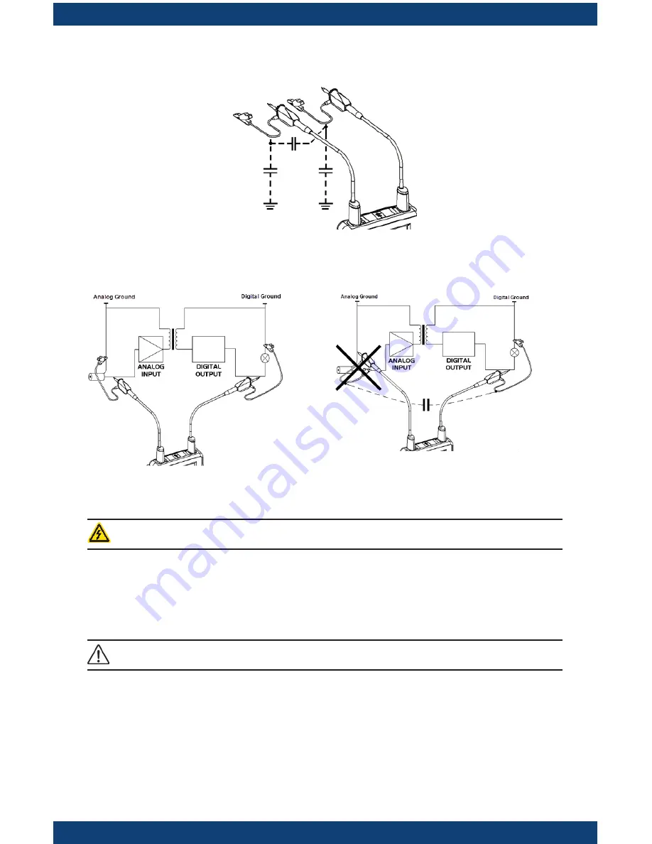
Distribution of stray capacitors:
Considering the stray capacitances, it is imperative to correctly connect the reference
conductors for each probe The conductors should preferably be connected to the cold
points to avoid the transmission of noise by the stray capacitance between modes.
The noise of the digital ground (earth) is sent to the analog input by the stray capaci-
tance.
NOTE:
In order to prevent electric shocks or possible fires, never use accessories on which the
casing is accessible if it has a voltage of > 30Vrms compared to the ground.
10:1 Probe Calibration
To obtain optimum response, the probe’s low frequency compensation must be
adjusted.
NOTE:
To carry out this adjustment,
the two channels of your oscilloscope must be
disconnected
from the measured circuits before opening the battery housing cover.


