9 : EG IN ( Egress Input)
A Normally Open (N.O.) input terminal referring to (-) ground. With the help of connecting a
normally open button to activate Output 1 for door opening like using Codes/Cards.
Egress button is usually put inside the house near the door. More than one egress buttons can be
connected in parallel to this terminal. Leave this terminal open if not used.
See Programming Locations 90 for more information about the Egress Button with programmable
features.
10 : KEY ACT O/P (Keypad Active Output)
An NPN transistor open collector output with maximum power rating of 24VDC/100mA sink. It is
equivalent to an N.O. (Normally Open) terminal referring to ground. It can be used to drive small
power device, such as a relay or a low power control point for other equipment.
11 : DU OUT (Duress Output)
An NPN transistor open collector output with maximum power rating of 24VDC/100mA sink. It is
equivalent to an N.O. (Normally Open) terminal switching to (-) ground after the Duress Code is
entered. Use it to trigger an alarm zone of a security system, or turn on a buzzer to notify a guard.
12 : (-) GND (Common Ground)
A grounding point of the keypad that is common to terminal 2.
13 : DOOR SENS N.C. (Door Position Sensing Input -- Normally Close)
A Normally Closed (N.C.) sensing point referring to (-) ground, with the help of a normally closed
magnetic contact monitors the open or close status of the door. It initiates the following functions
for the system. Connect it with jumper to (-) Ground if not used.
a) Door Auto Re-lock
The system immediately re-locks the door after it is re-closed before the end of the programmed
time for output 1. It prevents unwanted “tailgate” entry.
b) Door Forced Open Warning
The keypad generates “door forced open” warning instantly once the door is forced to open
without a valid user Code, Card or egress button. The warning lasts as long as the time
programmed (1-999 sec). It can be stopped with an User Code or card for output 1 at anytime.
See programming Location 80 for the details.
c) Door Propped-up Warning
The keypad generates propped-up warning beeps while the door is left open longer than the
allowable time programmed. The warning will last as long as the door is open until re-closed. See
programming Location 81 for the details.
d) Inter-lock Control
The inter-lock control output always goes to (-) while the door is open, which gives signal to
disable the partner keypad in an inter-lock system. See the Inter-lock terminal 15 description for
more information.
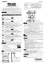
2) Multi-station Access Control Door Lock
Description
This is an expansion of application (1). The DK-2852 is expandable to a multi-station system for
user convenience with the auxiliary readers AR-2802 and/or the auxiliary reader-keypads
AR-2806, AR-2807 &r AR-2809. Total 3 auxiliary readers or reader-keypads can be connected in
parallel with the Data I/O Bus and they provide the same functions like the master keypad in
using cards and user codes.
Note:
Keep
Operation Mode
setting of the keypad in
“Keypad Mode (default)”
with
Location
(–) COMMON GND
(+) POWER SUPPLY
DATA I/O BUS
DK-2852
(MASTER KEYPAD)
AR-2802S OR
AR-2802A
(AUXILIARY READER)
ELECTRIC LOCK
System Connection
AR-2806 OR
AR-2807 OR
AR-2809
(AUXILIARY KEYPAD-READER)
94= 0
in this application.
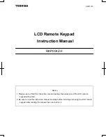
AR-2802S OR
AR-2802A
(–) COMMON GND
(+) POWER SUPPLY
DATA I/O BUS
Wiring Diagram
AR-2806 OR
AR-2807 OR
AR-2809
AUXILIARY
READER
AUXILIARY
KEYPAD-READER
EGRESS BUTTON
(INSIDE THE HOUSE)
MORE EGRESS
BUTTONS CAN
BE CONNECTED
IN PARALLEL
AD-1312 OR AP-960
DK-2852
LED
DATA
I/O
TAMPER
N.C.
(+) (–)
12-24V DC
LED
DATA
I/O
TAMPER
N.C.
(+) (–)
12-24V DC