background image

22


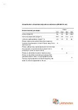
Classification of mechanically active substances (EN 60721-3-3) 


Environmental parameter 

Class 

3S1  3S2 

3S3  3S4 

a) Sand [mg/m

3

No 

30 

300  3000 

b) Dust (suspension) [mg/m

3

0.01 

0.2 

0.4 

4.0 

c) Dust (sedimentation) [mg/(m

2

h) 

0.4 

1.5 

15 

40 

Places where precautions have been taken to 
minimize the presence of dust. Places away from 
dust sources 


Places without any special precaution to minimize 
the presence of sand or dust, however not in 
proximity to sand or dust sources 


Places in proximity to sand or dust sources 


Places in proximity to working processes that 
generate sand or dust, or in geographic areas 
having a high proportion of sand brought by the 
wind or of dust suspended in the air 


Содержание Fluxpower HE 10 kVA

Страница 1: ...INSTALLATION AND START UP MANUAL EN Fluxpower HE 10 kVA Fluxpower HE 15 kVA Fluxpower HE 20 kVA Fluxpower HE 30 kVA Fluxpower HE 40 kVA Fluxpower HE ...

Страница 2: ...2 ...

Страница 3: ...3 WARNING This is a Class A UPS Product In a domestic environment this product may cause radio interference in which case the user may be take additional measures ...

Страница 4: ... 3 7 Maintenance 14 2 3 8 Storage 15 2 4 Environmental protection 15 2 4 1 ISO 14001 certification 15 2 4 2 Recycling of packing materials 15 2 4 3 Device disposal 15 3 Installation 16 3 1 Receipt of the UPS 16 3 1 1 Storage 16 3 2 Handling of the UPS 16 3 3 Positioning and installation 17 3 3 1 Base plan static load and weights 18 3 3 2 Overall dimensions minimum distances from the walls and vent...

Страница 5: ...ing BCB Fluxpower HE 10 15 20 kVA 36 4 5 AS553 external battery 37 4 5 1 Dimensions and weights 38 4 5 2 7 Ah 9 Ah 12 Ah 12 V battery connection and positioning 120 elements 40 4 5 3 Connections 42 4 6 Serial interfaces 42 4 7 Relay card connection optional 44 4 8 Back feed protection optional only for 30 40 kVA 46 5 Start up and shutdown 47 5 1 Preliminary checks 47 5 2 Start up procedure 47 5 3 ...

Страница 6: ...Ah 9Ah battery protection 33 Figure 12 7 Ah 9 Ah battery connection 34 Figure 13 7 Ah 9 Ah battery connected 35 Figure 14 Fuses positioning on the fuse holder BCB 36 Figure 15 Base planof the external battery cabinet 38 Figure 16 Dimensions of the external battery cabinet 38 Figure 17 Cardboard 7 Ah 9 Ah 12 Ah battery protection 40 Figure 18 7 Ah 9 Ah 12 Ah battery connection 40 Figure 19 7 Ah 9 A...

Страница 7: ...0 kVA Fluxpower HE 40 kVA STORING DOCUMENTATION This manual and any other supporting technical documentation relating to the product must be stored and made accessible to personnel in the immediate vicinity of the UPS FURTHER INFORMATION In the event that the information provided in this manual is not sufficiently exhaustive please contact the manufacturer of the device whose details are available...

Страница 8: ...UPS and to guide the installer or the user through the installation of the unit in its using environment The installer or the user must read and correctly perform the instructions included in the present manual with particular reference to the requirements regarding safety in compliance with the current regulations READ THE TECHNICAL DOCUMENTATION Before installing and using the device make sure y...

Страница 9: ...n ratings The plate is fixed outside on the rear of UPS CHECK THE TECHNICAL CHARACTERISTICS Before carrying out any installation or start up operation on the UPS make sure its technical characteristics are compatible with the AC supply line and with the output loads Figure 1 Rating plate of Fluxpower HE ...

Страница 10: ...h only when certified by the manufacturer 2 3 3 TRANSPORT AND HANDLING Avoid bending or deforming the components and altering the insulation distances while transporting and handling the product UNDISTRIBUTED WEIGHT The weight of the UPS is not uniformly distributed Pay attention when lifting Please inspect the device before installing it In case any damage is observed from the conditions of the p...

Страница 11: ...MENTAL CONDITIONS Fluxpower HE is designed for normal climatic and environmental operating conditions as defined in the technical specification altitude ambient operating temperature relative humidity and environmental transport and storage conditions It is necessary to implement specific protective measures in case of unusual conditions harmful smoke dust abrasive dust humidity vapor salt air bad...

Страница 12: ...be installed according to the requirements of HD 384 4 42 S1 A2 and in compliance with standard IEC 60364 4 482 Chapter 482 protection against fire Before connecting the unit to the distribution network make sure you have received the approval of the relevant electrical power distribution authority as provided for by the current national regulations All the electrical connections must be carried o...

Страница 13: ...andards technical equipment and accident prevention regulations The device can be started operated and disconnected only by authorized personnel The settings can only be changed using the original interface software INJURY HAZARD DUE TO ELECTRIC SHOCK During operation Fluxpower HE converts power characterized by high voltages and currents All the doors and the covers must remain closed INJURY HAZA...

Страница 14: ...tors which discharge slowly Thus we recommend to wait at least 5 minutes before opening the device doors INJURY HAZARD DUE TO ELECTRIC SHOCK Any operation must be carried out only when voltage is absent and in compliance with safety directives Make sure the battery circuit breaker that may be placed near the battery has been opened Isolate the device completely by operating the external circuit br...

Страница 15: ...ts vermin 2 4 ENVIRONMENTAL PROTECTION 2 4 1 ISO 14001 CERTIFICATION AEG POWER SOLUTIONS is particularly sensitive to the environmental impact of its products That is why Fluxpower HE has been manufactured with cutting edge eco design criteria ISO 14001 certification Special care was taken in using fully recyclable materials and in reducing the amounts of raw materials used 2 4 2 RECYCLING OF PACK...

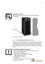
Страница 16: ...kage normally ensures protection from humidity and possible damages during transport Do not store the UPS outdoors RISK OF DAMAGE DUE TO INAPPROPRIATE STORAGE For the environmental storage conditions refer to the indications given for the installation of the device The device must only be stored in rooms protected from dust and humidity The device cannot be stored outdoors 3 2 HANDLING OF THE UPS ...

Страница 17: ...liance with the current legislation please refer to the Overall dimensions minimum distances from the walls and ventilation section SPECIAL ENVIRONMENTAL CONDITIONS It is necessary to implement specific protective measures in case of unusual environmental conditions harmful smoke dust abrasive dust humidity vapor salt air bad weather or dripping explosive dust and gas mixture extreme temperature v...

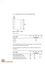
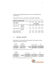
Страница 18: ... the UPS weight and to ensure its steady and safe support Its carrying capacity must be adequate for the static loads indicated in the table below Power kVA 10 15 20 30 40 Three phase Weight without battery kg 100 110 140 Weight with battery max kg 285 275 Static load without battery kg m2 347 381 486 Static load with battery max kg m2 989 954 Figure 3 Base plan ...

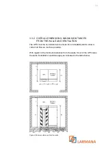
Страница 19: ... be so installed as to ensure its serviceability and to allow a correct air flow as much as possible With regard to the minimum distances from the walls for all of the UPS sizes the same installation conditions apply as indicated in the table below Figure 4 Minimum distances from the walls ...

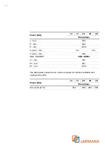
Страница 20: ...40 H mm 1200 X min mm 50 100 Y min mm 500 ADD CABINET COD AS553 L1 mm 503 P1 mm 647 H1 mm 1200 The table below shows the air volume required for optimal ventilation and cooling of the UPS Power kVA 10 15 20 30 40 Three phase Air volume m3 h 500 600 800 900 ...

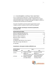
Страница 21: ...ing to the technical specification of Fluxpower HE Environmental parameter Minimum operating temperature C 10 Maximum operating temperature C 40 Minimum relative humidity 5 Maximum relative humidity 95 Condensation No Precipitation with wind rain snow hail etc No Water with an origin other than rain No Ice formation No Classification of biological conditions EN 60721 3 3 Environmental parameter Cl...

Страница 22: ...autions have been taken to minimize the presence of dust Places away from dust sources X Places without any special precaution to minimize the presence of sand or dust however not in proximity to sand or dust sources X Places in proximity to sand or dust sources X Places in proximity to working processes that generate sand or dust or in geographic areas having a high proportion of sand brought by ...

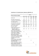
Страница 23: ... 3 0 35 175 h Ozone mg m3 0 004 0 01 0 01 0 1 0 3 2 0 i Nitric oxide expressed in equivalent values of nitrogen dioxide mg m3 0 01 0 1 0 1 1 0 9 0 20 Places where atmosphere is strictly monitored and regulated clean spaces category X Places where atmosphere is permanently monitored X Places located in rural and urban regions where industrial activities are few and where traffic is moderate X Place...

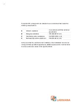
Страница 24: ... specification B Biological conditions 3B1 EN 60721 3 3 C Chemically active substances 3C2 EN 60721 3 3 S Mechanically active substances 3S2 EN 60721 3 3 In the event that the environmental conditions of the installation room do not comply with the specified requirements additional precautions must be taken to reduce excessive values to the specified limits ...

Страница 25: ...mmendations are only an indication as the UPS manufacturer is not responsible for the electrical installation In any case we recommend to carry out the installation and the electrical input and output connections in compliance with the local standards Cables must be selected bearing in mind technical financial and safety aspects The selection and the sizing of cables from a technical viewpoint dep...

Страница 26: ...cess the terminals remove the protection remove the fixing bolts UPS 30 40 kVA The terminal boards are placed on the front of the UPS To access the terminals remove the front panel remove the fixing bolts MAINS CONNECTION The connection to the mains must be carried out with protection fuses between the mains and the UPS The use of differential protection devices in the line supplying the UPS is un...

Страница 27: ...Rectifier 3x25 3x32 3x32 3x70 3x70 Bypass Input cables mm2 Rectifier 4x6 4x6 4x10 4x25 4x25 Bypass Onput cables mm2 4x6 4x6 4x10 4x25 4x25 Battery cables mm2 3x6 3x6 3x6 3x16 3x16 4 1 TERMINAL BOARDS Fluxpower HE is provided with terminal boards for the connection of power cables and of auxiliary connections Figure 5 Terminal board Fluxpower HE Three phase 10 15 20 kVA Figure 6 Terminal board Flux...

Страница 28: ...ge currents to earth The connection points must be hermetically sealed to prevent air from being sucked through the cable passage RISK OF DAMAGES TO THE DEVICE DUE TO INCORRECT WIRING To connect the device follow the electrical drawing scrupulously and respect the polarity of cables 4 3 BATTERY BATTERIES INSTALLATION For battery installation please respect the prescriptions of the EN62040 1 standa...

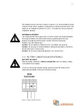
Страница 29: ...ries with the same number of block and capacity Replace only with original type Caution do not dispose of batteries in fire The battery may explode Caution do not open or mutilate batteries Released electrolyte is harmful to the skin and eyes It may be toxic Caution do not dump exhausted batteries in the environment 4 3 1 BATTERY CONNECTION AND POSITIONING BATTERY VOLTAGE After the battery install...

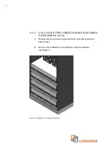
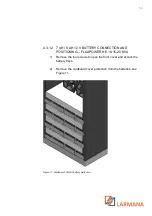
Страница 30: ...ECTION AND POSITIONING FLUXPOWER HE 10 KVA 1 Remove the four screws to open the front cover and access the battery trays 2 Remove the cardboard cover protection from the batteries see Figure 8 Figure 8 Cardboard 3 3 Ah battery protection ...

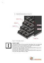
Страница 31: ...C sleeve for the connection to the negative pole and with RED PVC sleeve for the connection to the positive pole The termination of the cable 13 will be marked with BLACK PVC sleeve and that of the cable 13A with RED pvc sleeve The termination of the cable 15 will be marked with BLACK PVC sleeve and that of the cable 12 with RED pvc sleeve Figure 9 3 3 Ah battery connection ...

Страница 32: ...32 After the connection re insert the battery trays as shown in Figure 10 Put back and fix the front cover with the four screws Figure 10 3 3 Ah battery connected ...

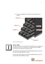
Страница 33: ...ION AND POSITIONING FLUXPOWER HE 10 15 20 KVA 1 Remove the four screws to open the front cover and access the battery trays 2 Remove the cardboard cover protection from the batteries see Figure 11 Figure 11 Cardboard 7Ah 9Ah battery protection ...

Страница 34: ...connection to the negative pole and with RED PVC sleeve for the connection to the positive pole The termination of the cable 13 will be marked with BLACK PVC sleeve and that of the cable 13A with RED pvc sleeve The termination of the cable 15 will be marked with BLACK PVC sleeve and that of the cable 12 with RED pvc sleeve Figure 12 7 Ah 9 Ah battery connection ...

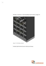
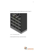
Страница 35: ...35 After the connection re insert the battery trays as shown in Figure 13 Put back and fix the front cover with the four screws Figure 13 7 Ah 9 Ah battery connected ...

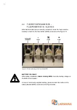
Страница 36: ...ntact on the fuse holder BCB as shown in the Figure 15 BATTERY VOLTAGE After battery installation before closing BCB check the battery voltage on the BCB circuit breaker In case of not directly supplied cabling please connect the cables to the battery breaker BCB as shown in the Figure below Figure 14 Fuses positioning on the fuse holder BCB ...

Страница 37: ... or is composed of two strings in parallel each composed of 60 monoblocks 30 30 Each monoblock is composed of 6 cells The size of the monoblocks can be 7 Ah 9 Ah or 12 Ah AS553 for 7Ah 9Ah and 12Ah battery blocks The battery circuit breaker and the battery fuses are installed inside the external battery cabinet see Figure 20 Concerning the installation of the external battery cabinet refer to the ...

Страница 38: ... 1 DIMENSIONS AND WEIGHTS The dimensions and weights of the external battery cabinet are indicated here Figure 15 Base planof the external battery cabinet Figure 16 Dimensions of the external battery cabinet ...

Страница 39: ...647 H mm 1200 L1 mm 500 P1 mm 625 L2 mm 50 Cabinet AS553 120 x 7 Ah 120 x 9 Ah 120 x 12 Ah 60 x 12 Ah Weight without battery kg 120 120 120 120 Weight with battery kg 408 459 645 385 Static load with battery kg m2 1255 1412 1984 1184 ...

Страница 40: ... the six screws to open the front cover and access the battery trays 2 Remove the cardboard cover protection from the batteries see Figure 17 3 Connect the wires as shown on the Figure 18 Figure 18 7 Ah 9 Ah 12 Ah battery connection Figure 17 Cardboard 7 Ah 9 Ah 12 Ah battery protection ...

Страница 41: ...ver with the six screws BATTERY VOLTAGE After the battery installation before closing BCB check the battery voltage on the BCB circuit breaker and connect battery cabinet to the UPS as indicated in paragraph 4 5 3 Figure 19 7 Ah 9 Ah 12 Ah battery connection Figure 20 Battery circuit breaker and fuses ...

Страница 42: ...on of the operating status and parameters RS232 USB is used for connection to the proprietary programming and control software MODBUS OPTIONAL is used for the transmission of data to the outside via MODBUS protocol RS485 with terminals PARALLEL OPTIONAL is used for communication between paralleled UPS units SNMP OPTIONAL is used for the external transmission of data via LAN NORMAL BYPASS SELECTOR ...

Страница 43: ...43 Figure 22 Interfaces of Fluxpower HE ...

Страница 44: ...IONAL Fluxpower HE in its full configuration is provided with a relay card for repeating alarms and operating statuses remotely Its electric connection is carried out directly on the terminals located on the card Figure 23 Relay card ...

Страница 45: ...10 11Open RL5 NORMAL MODE Alarm A16 BYPASS LOAD Not energized if alarm is present 14 15Closed DL5 On ECO MODE Status S7 BYPASS LOAD Energized if status is present 13 14Open RL6 BATTERY NOT DISCHARGING Not energized if battery discharge 17 18Closed DL6 On 16 17Open RL7 NORMAL MODE Status S4 INVERTER LOAD Energized if status is present 20 21Closed DL7 On ECO MODE Alarm A38 INV LOAD Not energized if ...

Страница 46: ...ith the back feed protection option only for 30 40 kVA it is mounted on the terminal board The fuse F12 that protects the power supply cable for contactor back feed protection relay RL1 PB244 back panel board Figure 24 Fuse F12 back feed protection 30 40 kVA ...

Страница 47: ...d to the relevant terminal boards the ground cable is properly connected the battery polarity is correct and the voltage is within the operating values the phase rotation of the line is correct and the voltage is within tolerance with the operating values the emergency power off EPO push button if installed is not pressed if not press it back to the rest position 5 2 START UP PROCEDURE EPO PUSH BU...

Страница 48: ...EASE WAIT UPS start up LED 1 is on input voltage present 7 RECTIFIER START UP PLEASE WAIT The IGBT rectifier bridge starts to modulate VDC voltage reaches the nominal value LED 3 is lit green DC voltage present 8 INVERTER START UP PLEASE WAIT The modulation of the inverter bridge is started The AC output voltage reaches the nominal value After a few seconds the static inverter switch is closed LED...

Страница 49: ...1 F2 F3 that they are inside the unit 2 After step 1 the UPS stops the starting sequence and shows one or more alarm messages Check the alarms indicated on the display and remove their causes Close RCB and try to restart the UPS 3 After step 2 the unit shows the alarm A15 Byp fault Make sure you have closed circuit breaker SBCB Check the protection fuses of the static bypass switch they are inside...

Страница 50: ...bypass without the need to de energize the loads MANUAL BYPASS To perform the switching procedure correctly make sure no alarms are present on the system During Manual Bypass the load is supplied directly by the input mains therefore continuous supply cannot be guaranteed to the loads No LCD Display Action Operating checks 1 A30 GENERAL ALARM Move the bypass selector SW to BYPASS The load is trans...

Страница 51: ...The bypass line is disconnected The display goes out 7 BLANK The load is supplied directly by the mains through the manual bypass switch The UPS is isolated Only for Fluxpower HE 30 40kVA with back feed protection option Open F12 Sectioning phase R Power supply contactor back feed relay contact RL1 PB244 back panel board ...

Страница 52: ...meters stored in the EEPROM All the LED s on the front panel are off 4 UPS START UP WAIT PLEASE The rectifier is supplied and the DC voltage reaches the nominal value All the LED s on the front panel are on The microprocessor checks that all the start up conditions are good for restart LED 1 lit green LED 8 lit orange 5 RECTIFIER START UP WAIT PLEASE The IGBT rectifier bridge starts to modulate VD...

Страница 53: ... START WAIT PLEASE The modulation of the inverter bridge is started The AC voltage reaches the nominal value The microprocessor checks the synchronization with the bypass line 12 START UP FROM MBCB MOVE BYP SWITCH Move the selector NORMAL BYPASS to NORMAL The load is transferred to the inverter LED 5 lit green 13 START UP END WAIT PLEASE The microprocessor checks that all the output parameters vol...

Страница 54: ...54 NOTES ...

Страница 55: ...55 NOTES ...

Страница 56: ...013 V1 Technical data in this document does not contain any binding guarantees or warranties Content only serves for information purposes and can be modified at any time We will make binding commitments only upon receipt of concrete enquiries and customer notification of the relevant conditions Due to the non binding nature of these terms we assume liability neither for the accuracy nor completene...

Отзывы: