4
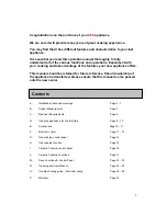
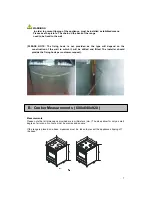
RECOMMENDED VENTILATION HEIGHT
- for ceramic cooktop model min. 24” above range
- for gas cooktop model min. 30” above range
When ranges are installed in close proximity
to vinyl finish cabinets,
those materials should be able to withstand temperature up to 75°C centigrade.
Alternatively, heat insulating barriers should be installed to avoid any
deterioration to the finish.
The equipment must not be installed near inflammable materials, such as curtains, cloths etc.
Pay particular attention to the position of the electric cable and gas pipe: they must
not touch any hot parts of the oven
The manufacturer will
not accept responsibility for damages to cabinetry where
manufacturer installation guidelines were not adhered to.
CONVERTING THE GAS-SUPPLY TO THE HOB BURNERS
Burners: auxiliary, semi-rapid, rapid, triple crown, griddle burner.
These burners are all fitted with injectors designed to create a primary input of air gauged for
each type of gas. This means that the air regulator does not have to be regulated. Proceed as
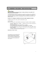
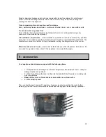
follows in order to convert from one type of gas to another: remove the grids, covers, holed flame
diffuser and the burner supports (fig. 7); replace the holed injectors as indicated in 7/C according
to the type of gas used (see table 1); put the burner supports, flame diffusers, covers and grids
back in position; regulate the minimum output following the instructions in paragraph 1.7.
REGULATING THE MINIMUM OUTPUT OF THE HOB BURNERS
Normal/valve taps:
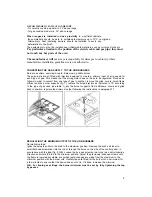
Ignite the burners and turn the knob to the maximum position. Remove the knob and insert a
small flat-head screwdriver into the rod or through the holes on the side of the control panel, in
accordance with the type (fig. 8 A/B). Loosen the by-pass screw by two turns in an anti-clockwise
direction and rotate the rod to the minimum position. Adjust the previously loosened screws until
the flame is lowered but stable, even when rapid changes are made from the maximum to the
minimum position with the burner cold. If safety taps are fitted, let the burner run on minimum for
a few minutes to ensure that the device does not cut in. If it does, increase the minimum.
N.B. For liquid gas settings, the burner minimum must be set by fully tightening the tap
by-passes
Содержание 24" 4006G-M
Страница 1: ...User s Manual 4006G M 24 Free Standing Dual Fuel Range User s Manual ...
Страница 29: ...29 ...


