4. Technical Overview
Advent Instruments Inc.
Line
Bypass
Terminal Equipment
CO Line
300 V
Peak
CAT
I
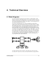
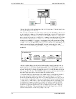
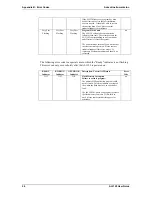
The next figure shows the configuration of the AI-5120 rear panel. The right most 2 mm
jack supplies DC power to the unit.
The connection to the PC (or any other host) is made via either the USB type B connector
or the 9 pin RS-232 connector. It is possible to transfer data to the AI-5120 over both the
USB and RS-232 ports simultaneously. However the TRsSim software is configured to
only use one of the two ports. The 9 pin RS-232 connector is configured as a DCE (Data
Communications Equipment). As such no cross over cable is required when making a
connection to a standard PC serial port. A minimum of three wires are required to make
a serial connection. They are TX Data (pin 2), RX Data (pin 3), and Ground (pin 5). The
AI-5120 can monitor the PC's RTS (pin 7) signal and control the state of the CTS (pin 8)
signal, but does not use them to communicate. The DSR (pin 6) and DTR (pin 4)
connections are internally tied together. The remaining pins (1 and 9) have no internal
connection.
USB
Digital In/Out
Gnd oA oB oC iA iB
RS-232
9 V 300 mA
Monitor
Speaker
2 Vrms
600 ohms
DCE
Advent Instruments Inc.
www.adventinstruments.com
Made in Canada
The BNC output connector can be used to monitor signals from the telephone line. Its
source impedance is 600 ohms with a maximum output level of 5 Volts peak-to-peak.
The 3 mm mono speaker jack to the left of the BNC monitor output performs a similar
function, and can drive a speaker or headphone directly. The load impedance should be
in the range of 8 to 32 ohms. Both the BNC output connector and mono audio jack have
adjustable output gain and are controlled from the TRsSim software
To the right of the BNC connector is a 6 pin terminal block. This connector provides 3
general purpose digital outputs and 2 general purpose digital inputs. The sixth pin
provides a ground connection to the AI-5120. The three digital outputs (A, B, C) are in
an open collector configuration. They can each sink up to 25 mA and are pulled high to
+5 volts with a 5.1 kohm resistor. All three digital outputs can be set either high or low.
An additional setting permits output A to mirror the bit pattern decoded by the FSK
demodulator, output B to go high if ringing is detected, and output C to go high if the
connected TE enters the off-hook state. The two digital inputs (A, B) have an input
impedance of 100 kohm. The maximum input level to detect a logic low is 0.8 volts,
while the minimum level to detect a logic high is 2.0 volts.
16
AI-5120 User Guide
Содержание AI-5120
Страница 1: ...Telephone Line Monitor AI 5120 User Guide Advent Instruments Inc Release 1 2d ...
Страница 4: ......

