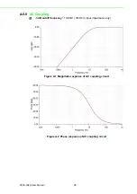
23
PCIE-1840 User Manual
Appendix A
S
pecifications
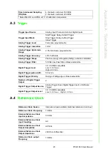
A.3
Trigger
A.4
Reference Clock
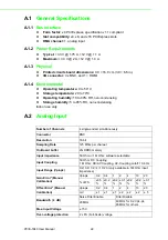
Time Interleaved Sampling
(TIS) Rate
4 channels combined, 500 MS/s
2 channels combined, 250 MS/s
* Noise filter ON and Within ±5 °C of calibration temperature
Trigger Input Source
Analog input Channels, External Digital inputs
Trigger Input Mode
Start Trigger, Delay-to-Start Trigger
Stop Trigger, Delay-to-Stop Trigger
Index Trigger
Analog Trigger Level
Full-scale, programmable
Analog Trigger resolution
16-bit
Analog Trigger Hysteresis
Range
2.5% Full-Scale, programmable
Analog Trigger Accuracy
±2% Full-Scale
Analog Trigger Slope
Positive (rising) or Negative (falling), software selectable
Analog Trigger Filter
50 KHz Low-Pass filter, software selectable
Digital Trigger Level
3.3 V COMS compatible
Low: 0.8 V max.;
High: 2.0V min
Digital Trigger pulse width
50 ns min.
Digital Trigger Polarity
Rising or Falling edge, software selectable
Number of Digital Trigger
Output
2
Digital Trigger Output Source
Analog Trigger Input, Digital Trigger input, or Software
Trigger
Digital Trigger Output Level
3.3 V COMS compatible
Low: 0.8 V max. ; High: 2.0 V min
Reference Clock Source
Internal on-board oscillator, External reference clock input
Reference Clock Frequency
10 MHz
External Reference Clock
input impedance
50 Ohm
External Reference Clock
input Coupling
AC
External Reference Clock
Output Compatible
LVPECL
External Reference Clock
Output Impedance
200 Ohm, Differential
Reference Clock output
Frequency
10 MHz
Содержание PCIE-1840
Страница 1: ...User Manual PCIE 1840 4 ch 16Bit 125 MS s High Speed Data Acquisition PCI Express Card ...
Страница 4: ...PCIE 1840 User Manual iv ...
Страница 12: ...PCIE 1840 User Manual 6 ...
Страница 13: ...Chapter 2 2 Installation ...
Страница 18: ...PCIE 1840 User Manual 12 ...
Страница 26: ...PCIE 1840 User Manual 20 ...
Страница 27: ...Appendix A A Specifications ...
Страница 35: ...Appendix B B Block Diagram ...


