background image

61

Chapter 6  

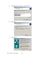
6.

Following the highlighted item, and click on "Next".

7.

Click on "Have Disk".

8.

Key in "D:\Drv_Lan\D_82559", then click on "OK".

Содержание PCA-6184

Страница 1: ...PCA 6184 Full size socket 478 Intel Pentium 4 processor based PCI ISA bus CPU card User s Manual ...

Страница 2: ...ation provided in this manual is intended to be accurate and reliable However Advantech Co Ltd assumes no responsibility for its use nor for any infringements upon the rights of third parties which may result from its use Acknowledgements AWARD is a trademark of AWARD Software Inc IBM and PC are trademarks of International Business Machines Corporation Intel and Pentium 4 are trademarks of Intel C...

Страница 3: ... Precautions 10 1 7 Jumper Settings 10 1 7 1 How to set jumpers 10 1 7 2 CMOS clear J1 10 Table 1 3 CMOS J1 11 1 7 3 Watchdog timer output J2 11 Table 1 4 Watchdog timer output J2 11 1 8 System Memory 11 Table 1 5 DIMM memory capacity sample calculation 12 1 8 1 Supplementary information about DIMMs 12 1 9 Memory Installation Procedures 12 1 10 Cache Memory 12 1 11 CPU Installation 13 1 11 1 Power...

Страница 4: ...Setup 28 3 1 Introduction 28 3 2 Entering Setup 28 Figure 3 1 Award BIOS Setup initial screen 28 3 3 Standard CMOS Setup 29 Figure 3 2 Standard CMOS features screen 29 3 3 1 CMOS RAM backup 29 3 4 Advanced BIOS Features 30 Figure 3 3 Advanced BIOS features screen 30 3 4 1 Virus Warning 30 3 4 2 CPU L1 L2 Cache 30 3 4 3 Quick Power on Self Test 30 3 4 4 First Second Third Other Boot Device 30 3 4 5...

Страница 5: ...Onboard Serial Port 2 2F8H IRQ3 36 3 6 8 UART Mode Select 36 3 6 9 RxD TxD Active 36 Figure 3 6 Integrated peripherals 2 36 3 6 10 Onboard Parallel Port 378 IRQ7 37 3 6 11 Parallel Port Mode ECP EPP 37 3 6 12 ECP Mode Use DMA 37 3 7 Power Management Setup 37 Figure 3 7 Power management setup 37 3 7 1 Power supply Type 38 3 7 2 Power Management 38 3 7 3 Video Off In Suspend 38 3 7 4 MODEM Use IRQ 3...

Страница 6: ...5 Windows 2000 Drivers Intel 82559 Setup Procedure 59 Chapter 7 Onboard Security Setup 66 7 1 Introduction 66 7 2 Windows 9X Drivers Setup Procedure 66 7 3 Windows NT Drivers Setup Procedure 68 7 4 Using the OBS Hardware Doctor Utility 71 Chapter 8 Ultra ATA Storage Driver Setup 74 8 1 Introduction 74 8 2 Features 74 8 3 Installation 75 8 4 Displaying Driver Information 79 Appendix A Programming t...

Страница 7: ...CPU Fan Power Connector CN14 98 Table B 11 CPU Fan Power Connector CN 14 98 B 12 Power LED and Keyboard Lock CN16 99 Table B 12 Power LED and Keyboard Lock CN 16 99 B 13 External Speaker Connector CN17 99 Table B 13 External Speaker Connector CN 17 99 B 14 Reset Connector CN18 100 Table B 14 Reset Connector CN 18 100 B 15 HDD LED Connector CN19 100 Table B 15 HDD LED Connector CN 19 100 B 16 ATX F...

Страница 8: ...Manual 6 Table B 22 DMA Channel Assignments 104 B 23 Interrupt Assignments 105 Table B 23 Interrupt Assignments 105 B 24 1st MB Memory Map 105 Table B 24 1st MB memory map 105 B 25 PCI Bus Map 106 Table B 25 PCI bus map 106 ...

Страница 9: ...It shows you how to configure the card to match your application and installation into your PC Sections include Introduction Features Specifications Board Layout Jumpers and Connectors Safety Precautions Jumper Settings System Memory Memory Installation Procedures Cache Memory CPU Installation ...

Страница 10: ...ngle or dual Intel 82559 10 100Base T Ethernet controller are available in the PCA 6184 series The high reliability and excellent per formance provided by Intel 82559 Ethernet controller are crucial for vari ous network applications Flexible I O expansion ports allow customers to optimize their need for four USB dual LAN port and additional PS 2 keyboard mouse port A CMOS data backup is stored in ...

Страница 11: ... your system through your network by sending a wake up frame or sig nal With this feature you can remotely upload download data to from systems during off peak hours 5 Message LED Chassis LEDs now act as information providers The way a particular LED illuminates indicates the stage the com puter is in A single glimpse provides useful information to the user 6 CMOS RAM backup When BIOS CMOS setup h...

Страница 12: ... ECC supported ECC parity DRAM only Modules can detect multi bit memory errors Correction of 1 bit memory errors 1 3 3 Input Output Bus interface PCI ISA bus PICMG compliant Enhanced parallel port Configurable to LPT1 LPT2 LPT3 or dis abled Standard DB 25 female connector provided Supports SPP EPP ECP Serial ports Two RS 232 ports with 16C550 UARTs or compatible with 16 byte FIFO buffer Supports s...

Страница 13: ... IRQ11 The watchdog timer is programmable with each unit equal to one second 255 lev els 1 3 7 Mechanical and environmental specifications Operating temperature 0 60 C depends on CPU Storage temperature 40 60 C 40 140 F Humidity 20 95 non condensing Power supply voltage 5 V 12 V Power consumption Typical 5V 7 4A 12V 320mA Pentium 4 1 8GHz 256MB DDR Board size 338 x 122 mm 13 3 x 4 8 Board weight 0...

Страница 14: ... gives instructions for connecting external devices to your card Table 1 1 Jumpers Label Function J1 CMOS Clear J2 Watchdog timer output selection Table 1 2 Connectors Label Function CN1 Primary IDE connector CN2 Secondary IDE connector CN3 Floppy drive connector CN4 Parallel port CN6 USB pory CN7 VGA connector CN8 10 100Base T Ethernet connector 1 CN9 Serial port COM1 CN10 Serial port COM2 CN11 P...

Страница 15: ...le OBS Alarm Open Disable OBS Alarm CN27 Extension I O board connector CN28 Extension I O board connector CN29 SM BUS Connector CN31 USB 0 1 CN32 USB 2 3 CN33 PS 2 Keyboard and Mouse connector CN34 10 100Base T Ethernet connector 2 CN46 Auxiliary 4 pin power connector Table 1 2 Connectors ...

Страница 16: ...l 8 1 5 Board Layout Jumper and Connector Locations Figure 1 1 Jumper and connecter locations CN46 J1 CN13 CN21 CN19 CN17 CN18 CN29 CN14 CN16 CN1 CN2 DIMM1 DIMM2 CN20 CN3 CN4 CN10 CN6 CN9 CN8 CN7 CN11 CN12 CN27 CN28 CPU J2 CN22 ...

Страница 17: ...9 Figure 1 2 Extension I O daughter board ...

Страница 18: ...n or turn OFF a jumper you remove the clip Sometimes a jumper consists of a set of three pins labeled 1 2 and 3 In this case you connect either pins 1 and 2 or 2 and 3 A pair of needle nose pliers may be useful when setting jumpers Warning Always completely disconnect the power cord from your chassis whenever you work with the hardware Do not make connections while the power is on Sensitive electr...

Страница 19: ...g timer output J2 The PCA 6184 contains a watchdog timer that will reset the CPU or send a signal to IRQ11 in the event the CPU stops processing This feature means the PCA 6184 will recover from a software failure or an EMI problem The J2 jumper settings control the outcome of what the com puter will do in the event the watchdog timer is tripped Table 1 3 CMOS J1 Function Jumper Setting Keep CMOS ...

Страница 20: ... module along the plastic guides on both ends of the socket Then press the DIMM module right down into the socket until you hear a click This is when the two handles have automatically locked the mem ory module into the correct position of the DIMM socket To remove the memory module just push both handles outward and the memory mod ule will be ejected by the mechanism in the socket 1 10 Cache Memo...

Страница 21: ...lign the CPU so it is parallel to the socket and the notches on the corners of the CPU correspond with the notches on the inside of the socket Gently slide the CPU in It should insert easily If it does not insert easily pull the lever up a little bit more 3 Press the lever down The plate will slide forward You will feel some resistance as the pressure starts to secure the CPU in the socket This is...

Страница 22: ...PCA 6184 ed 1 User s Manual 14 ...

Страница 23: ...15 CHAPTER 2 Connecting Peripherals This chapter tells how to connect peripherals switches and indicators to the PCA 6184 board ...

Страница 24: ...nector Unlike floppy drives IDE hard drives can connect in either position on the cable If you install two drives to a single connector you will need to set one as the master and the other as the slave You do this by setting the jumpers on the drives If you use just one drive per connector you should set each drive as the master See the documentation that came with your drive for more information ...

Страница 25: ...rinter The PCA 6184 includes an onboard parallel port accessed through a 26 pin flat cable connector CN4 The card comes with an adapter cable which lets you use a traditional DB 25 connector The cable has a 26 pin connector on one end and a DB 25 connector on the other mounted on a retaining bracket The bracket installs at the end of an empty slot in your chassis giving you access to the connector...

Страница 26: ...ected The USB interface is accessed through a 10 pin flat cable connector CN6 The adapter cable has a 10 pin connector on one end and two USB connectors on the bracket The USB interface can be disabled in the system BIOS setup 2 5 VGA Connector CN7 The PCA 6184 includes a VGA interface that can drive conventional CRT displays CN7 is a standard 15 pin D SUB connector commonly used for VGA Pin assig...

Страница 27: ... port CN34 is located at top slot of the I O expension ports 2 7 Serial Ports CN9 COM1 CN10 COM2 The PCA 6184 offers two serial ports CN9 as COM1 and CN10 as COM2 These ports can connect to serial devices such as a mouse or a printer or to a communications network The IRQ and address ranges for both ports are fixed However if you want to disable the port or change these parameters later you can do...

Страница 28: ...Two 6 pin mini DIN connector CN11 and 33 on the card mounting bracket supports single board computer applications The card comes with an adapter to convert from the 6 pin mini DIN connector to a PS 2 keyboard connector and to a PS 2 mouse connector 2 9 External Keyboard Connector CN12 In addition to the PS 2 mouse keyboard connector on the PCA 6184 s ear plate there is also an extra onboard extern...

Страница 29: ...nal wireless infrared transmitting and receiving module This module mounts on the system case You must configure the setting through the BIOS setup see Chapter 3 2 11 CPU Fan Connector CN14 This connector supports cooling fans of with current up to 2A CN13 CPU CPU CN14 ...

Страница 30: ...n the pin assignments If a PS 2 or ATX power supply is used the system s power LED status will be as indicated below 2 12 2 External speaker CN17 CN17 is a 4 pin connector for an extenal speaker If there is no external speaker the PCA 6184 provides an onboard buzzer as an alternative To enable the buzzer set pins 3 4 as closed Table 2 2 PS 2 or ATX Power Supply LED Status Power Model LED PS 2 powe...

Страница 31: ...stem Manager The SNMP 1000 allows users to monitor the internal voltages temperature and fans from a remote computer through an Ethernet network CN29 can be connected to CN3 or CN6 of SNMP 1000 Please be care ful about the pin assignments pin 1 must be connected to pin 1 and pin2 to pin 2 on both ends of cable 2 12 6 Connecting to SNMP 1000 remote manager Use the 6 pin to 8 pin cable to connect th...

Страница 32: ...f you will not be using an ATX power connector make sure that pins 2 3 of CN20 are closed Warnings 1 Make sure that you unplug your power sup ply when adding or removing expansion cards or other system components Failure to do so may cause severe damage to both your CPU card and expansion cards 2 ATX power supplies may power on if certain motherboard components or connections are touched by metall...

Страница 33: ...25 2 13 2 Controlling the soft power switch Users can also identify the current power mode through the system s power LED see Section 2 12 1 ...

Страница 34: ...PCA 6184 ed 1 User s Manual 26 ...

Страница 35: ...27 CHAPTER 3 Award BIOS Setup This chapter describes how to set the card s BIOS configuration data ...

Страница 36: ...rned off 3 2 Entering Setup Turn on the computer and check for the patch code If there is a number assigned to the patch code it means that the BIOS supports your CPU If there is no number assigned to the patch code please contact Advan tech s applications engineer to obtain an up to date patch code file This will ensure that your CPU s system status is valid After ensuring that you have a number ...

Страница 37: ...pleted CMOS RAM data is auto matically backed up to Flash ROM If conditions in a harsh industrial enviroment cause a soft error BIOS will recheck the data and automati cally restore the original data for booting Figure 3 2 Standard CMOS features screen Note If you intend to update CMOS RAM data you have to click on DEL within two seconds of the CMOS checksum error display screen mes sage appearing...

Страница 38: ...ting item to save yourself valuable time 3 4 1 Virus Warning If enabled a warning message and alarm beep activates if someone attempts to write here The commands are Enabled or Disabled 3 4 2 CPU L1 L2 Cache Enabling this feature speeds up memory access The commands are Enabled or Disabled 3 4 3 Quick Power on Self Test Allows the system to skip certain tests while booting It will reduce the time ...

Страница 39: ...ing The typematic rate is the rate key strokes repeat as determined by the key board controller The commands are Enabled or Disabled Enabling allows the typematic rate and delay to be selected 3 4 10 Typematic Rate Chars Sec BIOS accepts the following input values characters second for type matic rate 6 8 10 12 15 20 24 30 3 4 11 Typematic Delay msec Typematic delay is the time interval between th...

Страница 40: ...creen contains the manufacturer s default values for the PCA 6184 as shown in Figure 3 4 Note To disable security select PASSWORD SET TING in the main menu At this point you will be asked to enter a password Simply press Enter to disable security When security is disabled the system will boot and you can enter Setup freely Note DRAM default timings have been carefully cho sen and should ONLY be ch...

Страница 41: ...fault setting 3 5 6 DRAM DATA Integrity Mode Select the size of Accelerated Graphics Port AGP aperture The aperture is a portion of the PCI memory address range dedicated for graphics memory address space Host cycles that hit the aperture range are for warded to the AGP without any translation The Choice 4M 8M 16M 32M 65M 128M 256M 3 5 7 Memory Frequency For Onboard UBS This should be enabled if y...

Страница 42: ...setting is ìDisabled 3 5 12 Delay Transaction The chipset has an embedded 32 bit posted write buffer to support delay transactions cycles Select Enabled to support compliance with PCI spec ification version 2 1 The Choice Enabled Disabled 3 5 13 Delay Prior to Thermal The chipset has an ambedded 32 bit posted write buffer to support delay transaction cycles Select Enabled to support compliance wit...

Страница 43: ...ave a different Mode timing 0 1 2 3 4 it is necessary for these to be inde pendent The default setting Auto will allow autodetection to ensure optimal performance 3 6 3 USB Controller This should be enabled if your system has a USB installed on the system board and you want to use it Even when so equipped if you add a higher performance controller you will need to disable this feature The choice E...

Страница 44: ...board Serial Port 1 3F8H IRQ4 The settings are Auto 3F8 IRQ4 2F8 IRQ3 3E8 IRQ4 2E8 IRQ3 and Disabled for the on board serial connector 3 6 7 Onboard Serial Port 2 2F8H IRQ3 The settings are Auto 3F8 IRQ4 2F8 IRQ3 3E8 IRQ4 2E8 IRQ3 and Disabled for the on board serial connector 3 6 8 UART Mode Select This item allows you to select UART mode The choices IrDA ASKIR Normal 3 6 9 RxD TxD Active This it...

Страница 45: ...al speed operation but in one direction only EPP allows bidirectional parallel port operation at maximum speed ECP allows the parallel port to operate in bidirectional mode and at a speed faster than the maximum data transfer rate ECP EPP allows normal speed operation in a two way mode 3 6 12 ECP Mode Use DMA This selection is available only if you select ECP or ECP EPP in the Parallel Port Mode f...

Страница 46: ... power mode You can choose Delay 4 sec If you do so then pushing the button for more than 4 seconds will turn off the system whereas pushing the button Disable default No power management Disables all four modes Min Power Saving Minimum power management Suspend Mode 1 hr and HDD Power Down 15 min Max Power Saving Maximum power management Suspend Mode 1 min and HDD Power Down 1 min User Defined All...

Страница 47: ... 7 8 Power on by Ring When Enabled an input signal on the serial Ring Indicator RI line in other words an incoming call on the modem awakens the system from a soft off state The choices Enabled Disabled 3 7 9 Power on by Alarm When Enabled your can set the date and time at which the RTC real time clock alarm awakens the system from Suspend mode The choices Enable Disable 3 8 PnP PCI Configurations...

Страница 48: ... 9 PC Health Status 3 9 1 CPU Warning Temperature This item will prevent the CPU from overheating The choices 30 120 3 9 2 Current System Temperature This shows you the current system temperature 3 9 3 Current CPU Temperature This shows you the current CPU speed Note This is left Disabled Select Enabled to reset Extended System Configuration Data ECSD if you have installed a new add on card and yo...

Страница 49: ...ge Press Enter 2 If the CMOS is good or if this option has been used to change the default password the user is asked for the password stored in the CMOS The screen will display the following message Enter the current password and press Enter 3 After pressing Enter ROM password or the current password user defined you can change the password stored in the CMOS The password must be no longer than e...

Страница 50: ...MOS memory of the chipset The micropro cessor will check this every time you turn your system on and compare this to what it finds as it checks the system This record is required for the system to operate 3 13 Exit Without Saving Selecting this option and pressing Enter lets you exit the setup program without recording any new values or changing old ones ...

Страница 51: ...Chipset Software Installation Utility This utility software installs to the Win dows INF files that outline to the oper ating system how the componentswill be configured This utility has to be installed before other drivers ...

Страница 52: ...fore you begin it is important to note that most display drivers need to have the relevant software application already installed in the system prior to installing the enhanced display drivers In addition many of the installation procedures assume that you are familiar with both the rele vant software applications and operating system commands Review the relevant operating system commands and the ...

Страница 53: ... Manager Integrates superior video features These include filtered sealing of 720 pixel DVD content and MPEG 2 motion compensation for soft ware DVD Note This utility is used for the following versions of Windows system and it has to be installed before installing all the other drivers Windows 95 4 00 950 Original release Windows 95 4 00 950a OSR1 Windows 95 4 00 950b OSR2 without USB Supplement W...

Страница 54: ... system s CD ROM drive In a few seconds the software installation main menu appears Move the mouse cursor over the Auto button under the CSI UTILITY heading a message pops up telling you to install the CSI utility before other device drivers as shown in the following figure Click on this button ...

Страница 55: ...47 Chapter4 2 Click Next when you see the following message 3 Click Yes when you see the following message ...

Страница 56: ...PCA 6184 ed 1 User s Manual 48 4 Click Next when you see the following message 5 When the following message appears click Finish to complete the installation and restart Windows ...

Страница 57: ...er5 CHAPTER 5 AGP SVGA Setup The PCA 6184 features an onboard VGA interface This chapter provides instructions for installing and operating the software drivers on the display driver CD included in your package ...

Страница 58: ...t is important to note that most display drivers need to have the relevant software application already installed in the system prior to installing the enhanced display drivers In addition many of the installation procedures assume that you are familiar with both the rele vant software applications and operating system commands Review the relevant operating system commands and the pertinent sectio...

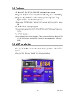
Страница 59: ...0 MHz DAC allows 85 Hz refresh at 1600 x 1200 resolu tion Complete local language support Power management for full VESA DPMS and EPA Energy Star com pliance AGP 1 0 interface Integrates superior video features These include filtered sealing of 720 pixel DVD content and MPEG 2 motion compensation for software DVD 5 3 VGA Installation First insert CD drive Then follow the Icons for your PCA Series ...

Страница 60: ...PCA 6184 ed 1 User s Manual 50 1 In the Setup click on next 2 In the Installation Information choose turbo mode or standard Then click on Next ...

Страница 61: ...51 Chapter5 3 The installaion is complete click on Yes to restart the system ...

Страница 62: ...PCA 6184 ed 1 User s Manual 52 ...

Страница 63: ... LAN Configuration The PCA 6184 features onboard dual 10 100Base T Ethernet LAN This chapter gives detailed information on Ethernet configuration It shows you how to configure the card to match your application requirements ...

Страница 64: ... Master complies with PCI Rev 2 2 MAC PHY 10 100 Mbps interfaces Complies to IEEE 802 3 10Base T IEEE 802 3u 100Base T interfaces Fully supports 10Base T and 100Base TX operation Single RJ 45 connector gives auto detection of 10 Mbps or 100 Mbps network data transfer rates and connected cable types 32 bit Bus Master technology complies with PCI Rev 2 1 Plug and Play 6 3 Driver Installation The PCA...

Страница 65: ... Windows NT Drivers Intel 82559 Setup Procedure 1 In the Windows NT screen click on Start and select Set tings Then click on the Control Panel icon to select Network Note The CD ROM drive is designated as D throughout ...

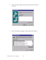
Страница 66: ...PCA 6184 ed 1 User s Manual 56 2 In the Network window select the Start Search tab Then click on Next 3 In the Select Network Adapter window click on Have Disk ...

Страница 67: ...insert the utility CD into the CD ROM drive The correct file path is D Drv_Lan 82559 When you have the correct file path click on OK 5 In the Network window select the Adapters tab Under Net work Adapters highlight Intel Pro Adapter Then click on Close ...

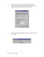
Страница 68: ...he Microsoft TCP IP Properties window select the IP Address tab Then select Specify an IP address Type in the IP Address and Subnet Mask details Then click on OK 7 In the Network Settings Change window click on Yes to restart the computer ...

Страница 69: ...p Proce dure 1 In the Windows 2000 screen click on Start and select set tings Then click on the Control Panel icon to select system 2 In the System Properties window select the Device Manager Note The CD ROM drive is designed as D through out this section ...

Страница 70: ...nual 60 3 In Device Manager screen click on Intel PRO 100 Server Adapter PILA84708 2 Then click on mice s right button You can see Property Click on Property 4 In the following screen to click on Update Driver 5 Click on Next ...

Страница 71: ...61 Chapter6 6 Following the highlighted item and click on Next 7 Click on Have Disk 8 Key in D Drv_Lan D_82559 then click on OK ...

Страница 72: ...PCA 6184 ed 1 User s Manual 62 9 To highlight the following item and click Next 10 Click Next 11 Click on Yes ...

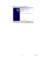
Страница 73: ...63 Chapter6 12 Click Finish to complete the installation ...

Страница 74: ...PCA 6184 ed 1 User s Manual 64 ...

Страница 75: ...hapter7 CHAPTER 7 Onboard Security Setup This chapter explains OBS concepts and provides instructions for installing the relevant software drivers This is done using the driver CD included in your PCA 6184 ...

Страница 76: ...em voltage sets which can be monitored include CPU core voltage 1 3 V 3 3 V according to Intel specifications Transmission voltage from CPU to chipset typically 1 8 V Chipset voltage typically 3 3 V Main voltage 5 V 12 V The negative system voltage sets which can be monitored include Main voltage 5 V 12 V 7 2 Windows 9X Drivers Setup Procedure 1 Insert the driver CD into your system s CD ROM drive...

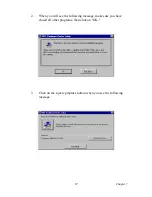
Страница 77: ...67 Chapter7 2 When you will see the following message make sure you have closed all other programs then click on OK 3 Click on the square graphics button when you see the following message ...

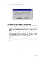
Страница 78: ... OK to complete the installation 7 3 Windows NT Drivers Setup Procedure 1 Insert the driver CD into your system s CD ROM drive In a few seconds the software installation main menu appears as shown in the following figure Click on the WIN NT button under the OBS DRIVERS heading ...

Страница 79: ...69 Chapter7 2 Click Next when you see the following message 3 Click Next when you see the following message ...

Страница 80: ...PCA 6184 ed 1 User s Manual 70 4 Click Next when you see the following message 5 Click Finish when you see the following message ...

Страница 81: ...ll be displayed and an error beep tone will activate to attract your attention OBS Hardware Doctor will show an icon on the right side of the bottom window bar This icon is the Terminate and Stay Resident TSR icon It will permanently remain in the bottom window bar and will activate warning signals when triggered by the onboard security system You can view or change values for various OBS settings...

Страница 82: ...on Start and select Pro grams and then OBS Hardware Doctor 2 It is recommended that you load the default values for all the OBS settings However if desired you can establish new conditions for voltage fan speed and temperature Please adjust TRANS_VCC high limit to 1 9V ...

Страница 83: ...73 Chapter8 CHAPTER 8 Ultra ATA Storage Driver Setup This driver must be installed to use the Intel Ultra ATA controller to improve storage subsystem performance and overall systemperformance ...

Страница 84: ...A subsystem 8 2 Features The driver enables fast Ultra ATA transfers by default Users no longer have to manually enable DMA transfers for each ATA and or ATAPI peripheral devices Each ATA channel has independent device timings transfers which allows PIO only and DMA capable devices to share the same ATA controller cable where one is the master and the other the slave with out restricting transfer ...

Страница 85: ...econds the software installation main menu appears as shown in the following figure Under the IDE DRIVERS heading click on the Install button Note Before installing this driver make sure the CSI utility has been installed in your system See Chapter 4 for information on installing the CSI utility ...

Страница 86: ...PCA 6184 ed 1 User s Manual 76 2 Click on Next when you see the following message 3 When you see the following message click on Yes to accept the License Agreement ...

Страница 87: ...77 Chapter8 4 Click on Next when you see the following message 5 Click on Next when you see the following message ...

Страница 88: ...PCA 6184 ed 1 User s Manual 78 6 When the following message appears click Finish to complete the installation and restart Windows ...

Страница 89: ...iver Information 1 From the desktop of Windows click on Start and select Pro grams Then select Intel Ultra ATA Storage Driver and then Companion 2 Click on the Device Parameters or the Storage Report tab to view related information ...

Страница 90: ...PCA 6184 ed 1 User s Manual 80 ...

Страница 91: ...chdog Timer The PCA 6184 is equipped with a watchdog timer that resets the CPU or generates an interrupt if processing comes to a standstill for any reason This feature ensures system reliability in industrial standalone or unmanned environments ...

Страница 92: ...e set from 1 to 255 seconds or 1 to 255 minutes Generates an interrupt or resets signal if the software fails to reset the timer after time out A 1 2 Reset Interrupt selection The J2 jumper is used to select reset or interrupt IRQ 11 in the event the watchdog timer is tripped See Chapter 1 for detailed jumper settings A 1 3 Programming the Watchdog Timer The I O port address of the watchdog timer ...

Страница 93: ...83 AppendixA Unlock W83627H Select register of watchdog timer Enable the function of the watchdog timer Use the function of the watchdog timer Lock W83627HF ...

Страница 94: ...he watch dog timer Disabled is set as default F5 hex write Set seconds or minutes as units for the timer Write 0 to bit 3 set second as counting unit default Write 1 to bit 3 set minute as counting unit F6 hex write 0 stop timer default 01 FF hex The amount of the count in seconds or minutes depends on the value set in register F5 hex This number decides how long the watchdog timer waits for strob...

Страница 95: ...Out dx al Dec dx Enable the function of watchdog timer Mov al 30h Out dx al Inc dx Mov al 01h Out dx al F7 hex read write Bit 6 Write 1 to enable keyboard to reset the timer 0 to dis able default Bit 5 Write 1 to generate a timeout signal immedi ately and automatically return to 0 default 0 Bit 4 Read status of watchdog timer 1 means timer is time out AA hex Write this address to I O port 2E hex t...

Страница 96: ...imeout interval as 10 seconds and start counting Mov al 0f6h Out dx al Inc dx Mov al 10 Out dx al Dec dx lock W83627HF Mov al 0aah Out dx al 2 Enable watchdog timer and set 5 minutes as timeout interval Mov dx 2eh unlock W83627H Mov al 87h Out dx al Out dx al Mov al 07h Select registers of watchdog timer Out dx al Inc dx Mov al 08h Out dx al ...

Страница 97: ...as counting unit Mov al 0f5h Out dx al Inc dx In al dx Or al 08h Out dx al Dec dx Set timeout interval as 5 minutes and start counting Mov al 0f6h Out dx al Inc dx Mov al 5 Out dx al Dec dx lock W83627HF Mov al 0aah Out dx al 3 Enable watchdog timer to be reset by mouse Mov dx 2eh unlock W83627H Mov al 87h Out dx al Out dx al ...

Страница 98: ...e function of watchdog timer Mov al 30h Out dx al Inc dx Mov al 01h Out dx al Dec dx Enable watchdog timer to be reset by mouse Mov al 0f7h Out dx al Inc dx In al dx Or al 80h Out dx al Dec dx lock W83627HF Mov al 0aah Out dx al 4 Enable watchdog timer to be reset by keyboard Mov dx 2eh unlock W83627H Mov al 87h Out dx al Out dx al ...

Страница 99: ...chdog timer Mov al 30h Out dx al Inc dx Mov al 01h Out dx al Dec dx Enable watchdog timer to be strobed reset by keyboard Mov al 0f7h Out dx al Inc dx In al dx Or al 40h Out dx al Dec dx lock W83627HF Mov al 0aah Out dx al 5 Generate a time out signal without timer counting Mov dx 2eh unlock W83627H Mov al 87h Out dx al Out dx al ...

Страница 100: ...Inc dx Mov al 08h Out dx al Dec dx Enable the function of watchdog timer Mov al 30h Out dx al Inc dx Mov al 01h Out dx al Dec dx Generate a time out signal Mov al 0f7h Out dx al Write 1 to bit 5 of F7 register Inc dx In al dx Or al 20h Out dx al Dec dx lock W83627HF Mov al 0aah Out dx al ...

Страница 101: ... VGA Connector Ethernet 10 100Base T RJ 45 Connec tor COM1 COM2 RS 232 Serial Port Keyboard and Mouse Connector External Keyboard Connector IR Connector CPU Fan Power Connector Power LED Connector External Speaker Connector Reset Connector HDD LED Connector ATX Feature Connector ATX Soft Power Switch H W Monitor Alarm Extension I O Board Connector DMA Channel Assignments Interrupt Assignments 1st ...

Страница 102: ...7 4 DATA 8 5 DATA 6 6 DATA 9 7 DATA 5 8 DATA 10 9 DATA 4 10 DATA 11 11 DATA 3 12 DATA 12 13 DATA 2 14 DATA 13 15 DATA 1 16 DATA 14 17 DATA 0 18 DATA 15 19 SIGNAL GND 20 GND 21 DISK DMA Request 22 GND 23 IO Write 24 GND 25 IO READ 26 GND 27 IO CHANNEL READY 28 GND 29 HDACKO 30 GND 31 IRQ14 32 N C 33 ADDR 1 34 N C 35 ADDR 0 36 ADDR 2 37 HARD DISK SELECT 0 38 HARD DISK SELECT 1 39 IDE ACTIVE 40 GND ...

Страница 103: ...3 GND 4 N C 5 DATA 6 6 FDEDIN 7 GND 8 INDEX 9 GND 10 MOTOR 0 11 GND 12 DRIVE SELECT1 13 GND 14 DRIVE SELECT 0 15 GND 16 MOTOR 1 17 GND 18 DIRECTION 19 GND 20 STEP 21 GND 22 WRITE DATA 23 GND 24 WRITE GATE 25 GND 26 TRACK 0 27 GND 28 WRITE PROTECT 29 GND 30 READ DATA 31 GND 32 HEAD SELECT 33 GND 34 DISK CHANGE 4 34 33 3 32 31 1 2 ...

Страница 104: ...w active Table B 3 Parallel Port Connector CN4 Pin Signal Pin Signal 1 STROBE 14 AUTOFD 2 D0 15 ERR 3 D1 16 INIT 4 D2 17 SLCTINI 5 D3 18 GND 6 D4 19 GND 7 D5 20 GND 8 D6 21 GND 9 D7 22 GND 10 ACK 23 GND 11 BUSY 24 GND 12 PE 25 GND 13 SLCT 26 N C 15 26 13 2 25 12 1 14 ...

Страница 105: ...or CN6 Pin USB1 Signal Pin USB2 Signal 1 5 V 6 5 V 2 UNV 7 UV 3 UV 8 UV 4 GND 9 GND 5 Chassis GND 10 N C Table B 5 VGA Connector CN7 Pin Signal Pin Signal 1 RED 9 VCC 2 GREEN 10 GND 3 BLUE 11 N C 4 N C 12 SDT 6 GND 14 V SYNC 7 GND 15 SCK 8 GND 7 3 2 8 1 6 9 10 4 5 5 15 1 11 10 6 ...

Страница 106: ... 7 COM1 COM2 Serial Port CN9 CN10 Table B 6 Ethernet 10 100Base T RJ 45 Connector CN8 CN34 Pin Signal Pin Signal 1 XMT 5 N C 2 XMT 6 RCV 3 RCV 7 N C 4 N C 8 N C Table B 7 COM1 COM2 RS 232 serial port CN9 CN10 Pin Signal 1 DCD 2 RXD 3 TXD 4 DTR 5 GND 6 DSR 7 RTS 8 CTS 9 RI ...

Страница 107: ...CN11 B 9 External Keyboard Connector CN12 Table B 8 Keyboard and Mouse Connector CN 11 Pin Signal 1 KB DATA 2 MS DATA 3 GND 4 VCC 5 KB CLOCK 6 MS CLOCK Table B 9 External Keyboard Connector CN 12 Pin Signal 1 CLK 2 DATA 3 NC 4 GND 5 VCC 5 3 1 2 4 6 ...

Страница 108: ... s Manual 98 B 10 IR Connector CN13 B 11 CPU Fan Power Connector CN14 Table B 10 IR Connector CN 13 Pin Signal 1 5 V 2 N C 3 IR_RX 4 GND 5 IR_TX Table B 11 CPU Fan Power Connector CN 14 Pin Signal 1 GND 2 12 V 3 Detect 1 ...

Страница 109: ...4 is for keyboard lock B 13 External Speaker Connector CN17 The CPU card has its own buzzer You can also connect it to the external speaker on your computer chassis Table B 12 Power LED and Keyboard Lock CN 16 Pin Function 1 LED power 5 V 2 NC 3 GND 4 Keyboard Lock 5 GND Table B 13 External Speaker Connector CN 17 Pin Function 1 5 VCC 2 GND 3 Internal buzzer 4 Speaker out ...

Страница 110: ...84 ed 1 User s Manual 100 B 14 Reset Connector CN18 B 15 HDD LED Connector CN19 Table B 14 Reset Connector CN 18 Pin Signal 1 Reset 2 GND Table B 15 HDD LED Connector CN 19 Pin Signal 1 Vcc LED 2 LED0 LED 1 1 ...

Страница 111: ...ixB B 16 ATX Feature Connector CN20 B 17 ATX Soft Power Switch CN21 Table B 16 ATX Feature Connector CN 20 Pin Signal 1 PS ON 2 VCC 3 VCC5VSB Table B 17 ATX Soft Power Switch CN 21 Pin Signal 1 3VSB 2 PWR BTN 1 1 ...

Страница 112: ... 5 Vcc USB3 15 GND USB1 6 Vcc USB2 16 GND USB0 7 GND USB3 17 5VSB 8 GND USB2 18 ACT LED LAN2 9 D USB1 19 LINK LAN 2 10 D USB0 20 SPEED 100Mbps Table B 19 Extension I O Board Connector CN 28 Pin Signal Pin Signal 1 TXC DVI 11 TX0 DVI 2 TXC DVI 12 TX0 DVI 3 FP_SDAT DVI 13 TXD LAN2 4 FP_SCLK DVI 14 GND 5 H_DEC DVI 15 RXIN LAN2 6 FP_VCC DVI 16 TXD LAN2 7 TX2 DVI 17 MS DATA PS 2 MS 8 TX2 DVI 18 RXIN LA...

Страница 113: ...ntroller 022 03F Motherboard resources 040 043 System timer 044 05F Motherboard resources 060 060 Standard 101 102 key or Microsoft Natural PS 2 061 061 System speaker 062 063 Motherboard resources 064 064 Standard 101 102 key or Microsoft Natural PS 2 065 06F Motherboard resources 070 073 System CMOS real time clock 074 07F Motherboard resources 080 090 Direct memory access controller 091 093 Mot...

Страница 114: ...Primary IDE channel 279 279 ISAPNP read data port 294 297 Motherboard resources 2F4 2F7 ISAPNP read data port 2F8 2FF Communication port COM2 376 376 Secondary IDE channel 378 37F Printer port LTP1 Table B 22 DMA Channel Assignments Channel Function 0 Available 1 Available 2 Floppy disk 8 bit transfer 3 Available 4 Cascade for DMA controller 5 Available 6 Available 7 Available Table B 21 System I ...

Страница 115: ...m CMOS real time clock 9 ISA Microsoft ACPI compliant system 12 ISA PS 2 compatible mouse 13 ISA Numeric data processor 14 ISA Primary IDE channel 11 PCI Standard OpenHCD USB host controller 21 PCI Intel PRO 100 Server adapter PILA8470B 2 22 PCI Intel PRO 100 Server adapter PILA8470B Table B 24 1st MB memory map Addr range HEX Device F0000h FFFFFh System ROM C8000h EFFFFh Unused C0000h C7FFFh VGA ...

Страница 116: ...us map Function AD_Select PCI IRQ GNT Onboard LAN2 AD22 PCI_IRQ22 GNT3 Onboard LAN1 AD21 PCI_IRQ21 GNT2 Onboard VGA AD20 PCI_IRQ20 GNT1 PCI slot 1 AD31 INT B C D A GNTA PCI slot 2 AD30 INT C D A B GNTB PCI slot 3 AD29 INT D A B C GNTC PCI slot 4 AD28 INT A B C D GNTD ...

Отзывы: