PCA-6184, ed. 1 User’s Manual
22
2.12 Front Panel Connectors (CN16, 17, 18, 19, 21&22)
There are several external switches to monitor and control the PCA-6184.
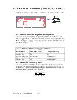
2.12.1 Power LED and Keyboard Lock(CN16)
CN16 is a 5-pin connector for the power on LED and Keyboard Lock.
Refer to Appendix B for detailed information on the pin assignments. If a
PS/2 or ATX power supply is used, the system's power LED status will be
as indicated below:
2.12.2 External speaker (CN17)
CN17 is a 4-pin connector for an extenal speaker. If there is no external
speaker, the PCA-6184 provides an onboard buzzer as an alternative. To
enable the buzzer, set pins 3-4 as closed
Table 2.2: PS/2 or ATX Power Supply LED Status
Power Model
LED (PS/2 power)
LED (ATX Power)
System On
On
On
System Suspend
Fast Flashes
Fast Flashes
System Off
Off
Slow Flashes
CPU
Содержание PCA-6184
Страница 1: ...PCA 6184 Full size socket 478 Intel Pentium 4 processor based PCI ISA bus CPU card User s Manual ...
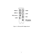
Страница 17: ...9 Figure 1 2 Extension I O daughter board ...
Страница 22: ...PCA 6184 ed 1 User s Manual 14 ...
Страница 34: ...PCA 6184 ed 1 User s Manual 26 ...
Страница 35: ...27 CHAPTER 3 Award BIOS Setup This chapter describes how to set the card s BIOS configuration data ...
Страница 55: ...47 Chapter4 2 Click Next when you see the following message 3 Click Yes when you see the following message ...
Страница 61: ...51 Chapter5 3 The installaion is complete click on Yes to restart the system ...
Страница 62: ...PCA 6184 ed 1 User s Manual 52 ...
Страница 72: ...PCA 6184 ed 1 User s Manual 62 9 To highlight the following item and click Next 10 Click Next 11 Click on Yes ...
Страница 73: ...63 Chapter6 12 Click Finish to complete the installation ...
Страница 74: ...PCA 6184 ed 1 User s Manual 64 ...
Страница 79: ...69 Chapter7 2 Click Next when you see the following message 3 Click Next when you see the following message ...
Страница 90: ...PCA 6184 ed 1 User s Manual 80 ...

