5
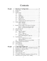
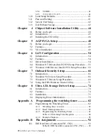
B.2
Floppy Drive Connector (CN3)....................................... 93
Table B.2:Floppy Drive Connector (CN3) ................... 93
B.3
Parallel Port Connector (CN4) ........................................ 94
Table B.3:Parallel Port Connector (CN4)..................... 94
B.4
USB Connector (CN6) .................................................... 95
Table B.4:USB Connector (CN6)................................ 95
B.5
VGA Connector (CN7) ................................................... 95
Table B.5:VGA Connector (CN7) ................................ 95
B.6
Ethernet Base-T Connector (CN8, CN34) ...................... 96
Table B.6:Ethernet 10/100Base-T RJ-45
Connector (CN8, CN34) ............................................... 96
B.7
COM1/COM2 Serial Port (CN9, CN10)......................... 96
Table B.7:COM1/COM2 RS-232 serial port (CN9,
CN10) ............................................................... 96
B.8
Keyboard and Mouse Connnector (CN11)...................... 97
Table B.8:Keyboard and Mouse Connector (CN 11) ... 97
B.9
External Keyboard Connector (CN12)............................ 97
Table B.9:External Keyboard Connector (CN 12) ....... 97
B.10
IR Connector (CN13) ...................................................... 98
Table B.10:IR Connector (CN 13)................................ 98
B.11
CPU Fan Power Connector (CN14) ................................ 98
Table B.11:CPU Fan Power Connector (CN 14).......... 98
B.12
Power LED and Keyboard Lock (CN16)........................ 99
Table B.12:Power LED and
Keyboard Lock (CN 16) .............................................. 99
B.13
External Speaker Connector (CN17)............................... 99
Table B.13:External Speaker Connector (CN 17) ........ 99
B.14
Reset Connector (CN18) ............................................... 100
Table B.14:Reset Connector (CN 18)......................... 100
B.15
HDD LED Connector (CN19)....................................... 100
Table B.15:HDD LED Connector (CN 19) ................ 100
B.16
ATX Feature Connector (CN20)................................... 101
Table B.16:ATX Feature Connector (CN 20) ............ 101
B.17
ATX Soft Power Switch (CN21) .................................. 101
Table B.17:ATX Soft Power Switch (CN 21) ............ 101
B.18
Extension I/O Board Connector (CN27)....................... 102
Table B.18:Extension I/O Board Connector (CN 27). 102
B.19
Extension I/O Board Connector (CN28)....................... 102
Table B.19:Extension I/O Board Connector (CN 28). 102
B.20
SM Bus Connector (CN29) ........................................... 103
Table B.20:SM Bus Connector (CN 29)..................... 103
B.21
System I/O Ports............................................................ 103
Table B.21:System I/O Ports ...................................... 103
B.22
DMA Channel Assignments.......................................... 104
Содержание PCA-6184
Страница 1: ...PCA 6184 Full size socket 478 Intel Pentium 4 processor based PCI ISA bus CPU card User s Manual ...
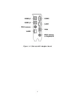
Страница 17: ...9 Figure 1 2 Extension I O daughter board ...
Страница 22: ...PCA 6184 ed 1 User s Manual 14 ...
Страница 34: ...PCA 6184 ed 1 User s Manual 26 ...
Страница 35: ...27 CHAPTER 3 Award BIOS Setup This chapter describes how to set the card s BIOS configuration data ...
Страница 55: ...47 Chapter4 2 Click Next when you see the following message 3 Click Yes when you see the following message ...
Страница 61: ...51 Chapter5 3 The installaion is complete click on Yes to restart the system ...
Страница 62: ...PCA 6184 ed 1 User s Manual 52 ...
Страница 72: ...PCA 6184 ed 1 User s Manual 62 9 To highlight the following item and click Next 10 Click Next 11 Click on Yes ...
Страница 73: ...63 Chapter6 12 Click Finish to complete the installation ...
Страница 74: ...PCA 6184 ed 1 User s Manual 64 ...
Страница 79: ...69 Chapter7 2 Click Next when you see the following message 3 Click Next when you see the following message ...
Страница 90: ...PCA 6184 ed 1 User s Manual 80 ...


