38
4.4 Counter Function
The MIC-3756 provides one 16-bit up Counter/Timer function.
Counter/Timer function can be configured by setting the
corresponding counter registers. Moreover, you can setup the
Counter/Timer mode by Counter Mode Register, as shown in
Table
4-11
.
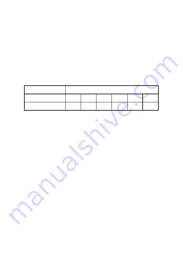
Table 4-11 Counter Mode Register
Counter Mode Register
Base Add.+ Ch
5
4
3
2
1
0
Abbreviation
CM5
CM4
CM3
CM2
CM1
CM0
Counter Mode Register
Counter Gate control: CM1, CM0
00 = stop counter
01 = DI16 as GATE high
10 = DI16 as GATE low
11 = No Gating
Interrupt Control Register: CM2
0 = disable interrupt
1 = Enable interrupt
CLK source control: CM3
0 = DI00
1 = 1MHz clock source on broad
DO00 output Control: CM5, CM4
00 = Digital Output DO00
01 = Counter output TC
Toggle
from low
10 =
Counter output TC
Table 4-12
shows the counter read back value register. Users can read
this register to get the current value of counter.
Table 4-13
show the
counter set value register. The register can set the initial value of
counter, and the MAX of initial value is 65535.
Содержание MIC-3756
Страница 2: ...ii This page is left blank for hard printing ...
Страница 7: ...1 Introduction 1 CHAPTER ...
Страница 8: ...2 This page is left blank for hard printing ...
Страница 13: ...7 Hardware Configuration CHAPTER 2 ...
Страница 14: ...8 This page is left blank for hard printing ...
Страница 20: ...14 2 3 Board Layout Fig 2 1 MIC 3756 board layout ...
Страница 22: ...16 This page is left blank for hard printing ...
Страница 23: ...17 Pin Assignment and Jumper Setting CHAPTER 3 ...
Страница 24: ...18 This page is left blank for hard printing ...
Страница 26: ...20 Fig 3 1 I O Connector pin assignments for the MIC 3756 ...
Страница 33: ...27 Operations CHAPTER 4 ...
Страница 34: ...28 This page is left blank for hard printing ...
Страница 49: ...43 Appendixes ...
Страница 50: ...44 This page is left blank for hard printing ...
Страница 56: ...50 Note Write 1 to the bit Fn in Interrupt Control Register clears the interrupt ...


