vii
IPC-622 User Manual
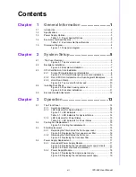
Contents
Chapter
1
General Information
............................1
1.1
Introduction ............................................................................................... 2
1.2
Specifications ............................................................................................ 2
1.3
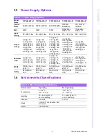
Power Supply Options............................................................................... 3
Table 1.1: Power Supply Options ................................................ 3
1.4
Environmental Specifications .................................................................... 3
Table 1.2: Environmental Specifications ..................................... 3
1.5
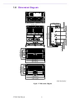
Dimension Diagram................................................................................... 4
Figure 1.1 Dimension diagram..................................................... 4
Chapter
2
System Setup
.......................................5
2.1
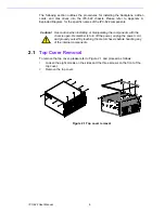
Top Cover Removal .................................................................................. 6
Figure 2.1 Top cover removal...................................................... 6
2.2
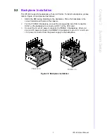
Backplane Installation ............................................................................... 7
Figure 2.2 Backplane installation................................................. 7
2.3
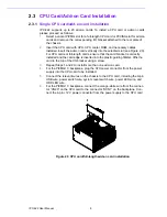
CPU Card/Add-on Card Installation .......................................................... 8
2.3.1
Single CPU card/add-on card installation ..................................... 8
Figure 2.3 CPU card/full-length add-on card installation ............. 8
2.3.2
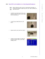
Dual CPU Card Installation on a Dual-Segment Backplane ......... 9
2.3.3
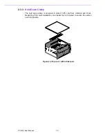
Hold Down Clamp ....................................................................... 10
Figure 2.4 Top cover with rubber pad........................................ 10
2.4
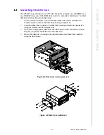
Installing Disk Drives............................................................................... 11
Figure 2.5 Disk drive housing removal ...................................... 11
Figure 2.6 Disk drive installation................................................ 11
2.5
Ear and Handle Attachment .................................................................... 12
Chapter
3
Operation
............................................13
3.1
The Front Panel ...................................................................................... 14
3.1.1
Switch and Buttons ..................................................................... 14
3.1.2
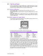
LED Indicators for System Status ............................................... 14
Figure 3.1 LED indicators .......................................................... 14
Table 3.1: LED Indicators for System Status............................. 14
3.1.3
LED Indicators for Power Status................................................. 15
Table 3.2: LED Indicators for Power Status .............................. 15
3.2
Cooling Fan Replacement....................................................................... 15
Figure 3.2 Cooling fan replacement........................................... 15
3.3
Filter Replacement .................................................................................. 16
3.3.1
Replacing the filter behind the front upper cover ........................ 16
Figure 3.3 Replacing the front upper cover filter........................ 16
3.3.2
Replacing the filter behind the front door .................................... 16
Figure 3.4 Replacing the front door filter ................................... 16
3.4
Power Supply Replacement.................................................................... 17
3.4.1
Redundant Power Supply Module .............................................. 17
Figure 3.5 Replacing the redundant power supply module ....... 17
Figure 3.6 Power cord socket orientation .................................. 17
3.4.2
Power Supply Module ................................................................. 18
Figure 3.7 Replacing the single power supply ........................... 18
Figure 3.8 Replacing the redundant power supply .................... 19
Содержание IPC-622 Series
Страница 1: ...User Manual IPC 622 Series 6U Multi Segment Rackmount Industrial Computer Chassis...
Страница 27: ...19 IPC 622 User Manual Chapter 3 Operation Figure 3 8 Replacing the redundant power supply...
Страница 28: ...IPC 622 User Manual 20...
Страница 36: ...IPC 622 User Manual 28 Table 4 22 PWR1 Pin 1 V12 Pin 4 GND Pin 2 GND Pin 5 V5...
Страница 37: ...Appendix A A Exploded Diagram...
Страница 38: ...IPC 622 User Manual 30 A 1 Exploded Diagram Figure A 1 Exploded diagram 1 Figure A 2 Exploded diagram 2...
Страница 39: ...Appendix B B Backplane Options...
Страница 41: ...33 IPC 622 User Manual Appendix B Backplane Options...

