

IPC-622 User Manual
26
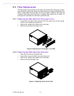
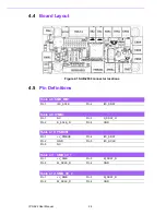
4.4
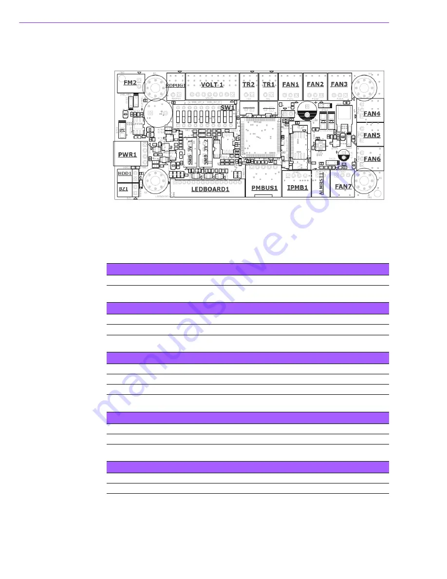
Board Layout
Figure 4.1 SAB-2000 connector locations
4.5
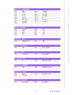
Pin Definitions
:8
:8
Table 4.8: SMB_MB1
Pin 1
I2C_SCLK
Pin 2
I2C_SDAT
Table 4.9: IPMB1
Pin 1
NC
Pin 3
S_SDAT_R
Pin 2
S_SCLK_R
Pin 4
GND
Table 4.10: PSBUS1
Pin 1
+V_PMBUS
Pin 4
I2C_SDAT
Pin 2
GND
Pin 5
I2C_SCLK
Pin 3
NC
Table 4.11: SMB_3V_1
Pin 1
+V_SMB
Pin 3
M_SDAT_R
Pin 2
M_SCLK_R
Pin 4
GND
Table 4.12: SMB_3V_2
Pin 1
+V_SMB
Pin 3
M_SDAT_R
Pin 2
M_SCLK_R
Pin 4
GND
Содержание IPC-622 Series
Страница 1: ...User Manual IPC 622 Series 6U Multi Segment Rackmount Industrial Computer Chassis...
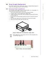
Страница 27: ...19 IPC 622 User Manual Chapter 3 Operation Figure 3 8 Replacing the redundant power supply...
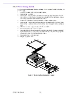
Страница 28: ...IPC 622 User Manual 20...
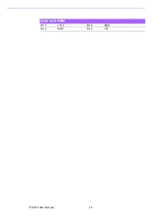
Страница 36: ...IPC 622 User Manual 28 Table 4 22 PWR1 Pin 1 V12 Pin 4 GND Pin 2 GND Pin 5 V5...
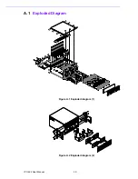
Страница 37: ...Appendix A A Exploded Diagram...
Страница 38: ...IPC 622 User Manual 30 A 1 Exploded Diagram Figure A 1 Exploded diagram 1 Figure A 2 Exploded diagram 2...
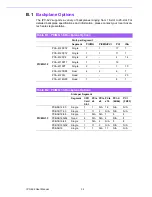
Страница 39: ...Appendix B B Backplane Options...
Страница 41: ...33 IPC 622 User Manual Appendix B Backplane Options...