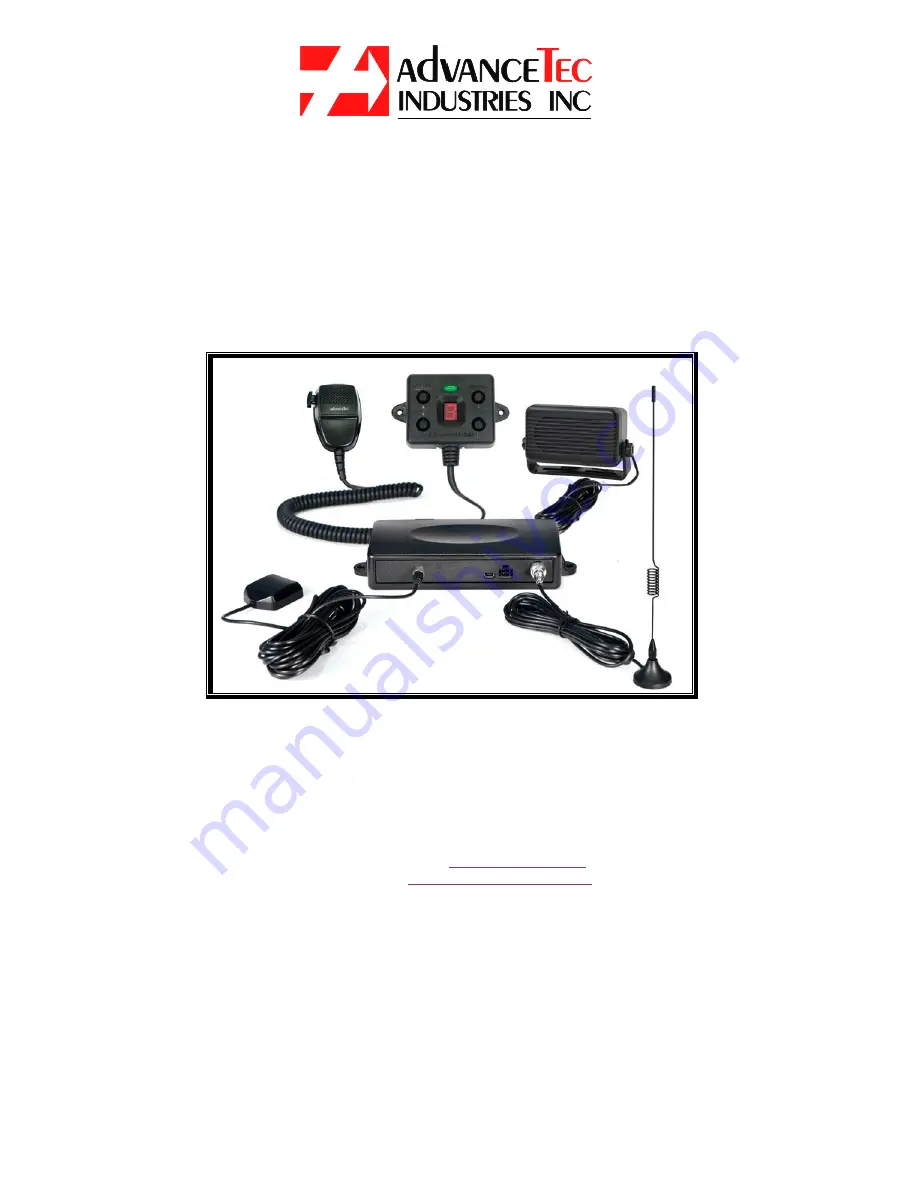
AdvanceTec AdvanceMobile AT3550A Скачать руководство пользователя страница 1


Advance

Mobile


Installation / User Manual 

Part No. AT3550A  


AdvanceTec Industries, Inc 1150 NW 163

rd

 Drive, Miami, FL 33169 

T: 305-623-3939 F: 305-623-3996 Toll Free: 1-800-881-8211 


 Company web site: 

www.advancetec.com 


 GPS services

www.advancemobilegps.com 


Содержание AdvanceMobile AT3550A

Страница 1: ...ation User Manual Part No AT3550A AdvanceTec Industries Inc 1150 NW 163rd Drive Miami FL 33169 T 305 623 3939 F 305 623 3996 Toll Free 1 800 881 8211 Company web site www advancetec com GPS services www advancemobilegps com ...

Страница 2: ... of Vehicular and GPS Antenna 10 Installation of Emergency PTT 10 11 Inserting SIM into Junction Box 11 12 Connecting Cables to Junction Box 12 13 System Registration and Programming 14 Making and receiving PTT call 14 Receiving incoming Cellular call 14 Turning AdvanceMobile OFF Optional Extra Accessories 15 17 AdvanceMobile Control Modules 18 Privacy Handset with Cradle 19 Palm Mic Specification...

Страница 3: ...ker and Junction Box and Magnetic Mount Antenna Consider the following guidelines when planning the installation DO use all mounting hardware provided DO ensure that cables are not placed under stress DO follow proper and connections DO crimp connectors securely DO NOT attach components to any part of the vehicle that is not rigid or is subject to excessive vibration DO NOT install components in a...

Страница 4: ...Operating the AdvanceMobile The AdvanceMobile will allow 1 PTT calls from the unit to a pre set private ID or group ID 2 PTT and Cellular calls to the unit 3 When used with the Optional Control Module PTT calls from the unit to a Group ID and 9 different Private ID numbers Set up of AdvanceMobile NOTE The AdvanceMobile requires an iDEN SIM card To acquire such a SIM card contact your local iDEN Pr...

Страница 5: ...d the cable out of sight to the location where you intend to mount the junction box 6 The speaker should be located at least 3 ft 1m from the visor mic Avoid placing the speaker where it faces the visor microphone B Mounting of the PTT 1 To attach the PTT to the gear lever strap the PTT around the gear lever using the Velcro strip attached with the cord facing down Diagram 2 Mounting Bracket Thumb...

Страница 6: ...ormance of the AdvanceMobile 1 The Microphone should be mounted either on the sun visor directly above and facing the driver or on the headliner just above and facing the driver One of the following two microphones will be supplied with this kit Facing the driver Diagram 3 2 The microphone supplied has a noise canceling feature so must be mounted facing the driver as shown in the picture above 3 T...

Страница 7: ...4 1 The DC power cable shipped with the AdvanceMobile is suitable for installation in most vehicles 2 Route the black lead of the main power cable to a convenient chassis ground and the red lead to the positive supply voltage connection points If it is necessary to penetrate the firewall try to use an existing opening 3 If there is no existing opening drill a new hole approximately 9 16 or 3 5cm i...

Страница 8: ...int 10 Route and connect the green lead to a convenient ignition switch supply point in the vehicle Note An ignition switch accessory terminal can be verified by measuring the terminal while operating the vehicle s key switch With the ignition key in the accessory ON position the terminal voltage should measure the vehicle s battery voltage With the switch in the OFF position it should measure nea...

Страница 9: ...onnect the antenna cable to the external antenna connector on the junction box Diagram 7 5 If you intend to make use of the GPS feature connect the GPS antenna cable to the GPS antenna connector on the junction box The GPS antenna is an optional extra that is available to be purchased from AdvanceTec 6 Feed the antenna cables out of sight to the location where you intend to mount the junction box ...

Страница 10: ...ic part that held the strips in place with the larger flat plastic part supplied with the PTT Screw the new plastic part in place 3 Feed the cable out of sight to the location where you intend to mount the 4 pin connector on the junction box Caution Make sure there is sufficient slack in the cable to allow the free movement of the gear lever without stretching the PTT cable Inserting SIM into Junc...

Страница 11: ... or replace the SIM card after installation has been completed the power cable must be disconnected from the Junction Box Connecting cables to Junction Box 1 Locate a position for the junction box beneath the dashboard on the pas senger s side of the vehicle or on the center side post between the front seats It must be protected from dirt and moisture and must be afforded adequate space for coolin...

Страница 12: ... a plastic tie or screw through the hole in the fuse s plastic housing System Registration and Programming 1 Once the AdvanceMobile is powered and the SIM is inserted it will begin the registration process onto the iDEN system The initial registration onto the iDEN system can take up to 3 minutes 2 Once the AdvanceMobile has successfully registered onto the iDEN system 5 short pulses will be heard...

Страница 13: ...iagram 12 3 Once the Private ID or Group ID has been successfully loaded proceed to permanently mount the junction box with the screws provided ensuring that all extra cabling is secured out of harms way Diagram 13 Making a PTT call to Private ID or Group ID programmed 1 Press and hold down the PTT button 2 Speak towards the visor microphone Mounting holes Mounting holes ...

Страница 14: ...phone Incoming Cellular call 1 To answer an incoming cellular call press and hold the PTT button for 3 seconds Once the incoming call is answered release the PTT to continue the cellular conversation 3 Speak towards the visor microphone 4 To end the cellular call press and hold down the PTT Turning AdvanceMobile OFF 1 When the car ignition is ON the AdvanceMobile will stay on 2 When the ignition i...

Страница 15: ...the AdvanceMobile powered press the UP or DOWN Channel Control Button Channel numbers from 1 to 9 will show in the Control Module screen Channel number 0 will show E and is used for an Emergency number 3 A flashing number in the screen indicates that the channel is open not programmed and available to be programmed 4 With a channel number flashing initiate a PTT call to the AdvanceMobile from the ...

Страница 16: ... the channel displayed is the channel selected and programmed When the PTT is pressed it will transmit on that channel 2 If the Display shows a slow flashing number 1 9 the channel is not programmed If the PTT is pressed a reject tone will be heard 3 If the Display shows a fast flashing number 1 9 a call is coming in from the remote user who is programmed into the AdvanceMobile on that channel num...

Страница 17: ...cate that the unit is back in the channel mode 7 The Channel and Volume selected will be saved when the Control Module is powered off and will resume when it is next powered up 8 If the Control Module looses communication with the main unit it will show 3 horizontal lines LED indicators Flashing red Unit not yet registered Steady Green Unit registered OK Blinking Green Unit registered OK and Ignit...

Страница 18: ...me way with the Privacy Handset as with the PTT described above 2 Lift the privacy handset out of the cradle and using the PTT button on the back of the privacy handset follow the instructions for making and receiving calls as set out above 3 A cellular call can be terminated by pressing and holding down the PTT button ...

Страница 19: ... with the AdvanceMobile plug the connector on the end of the coil cord of the Palm Mic into the corresponding RJ45 receptacle on Junction Box 2 Once connected the pressing of the switch on the Palm Mic will deactivate the Visor Mic and activate the Palm Mic ...

Страница 20: ...nna Impedance 50 Ohms SIM card 3 Volts SIM cars PIN Programmed by user one time automatically introduced Onward PIN saved on Non Volatile memory Receiver Specifications Frequency Range 851 min 870 MHz Max in the 800MHz band Frequency Range 935 min 941 MHz max in the 900MHz band Channel Spacing 25 N A KHz Sensitivity 10 BER 111dBm max Strong Signal BER 0 1 max RF level 80 dBm Overload Immunity 10 m...

Страница 21: ...us Emissions 13dBm max per FCC and IPU R requirements iDEN GPS Specifications GPS Module Sensitivity 152 dBm Tracking 142 dBm Acquisition Protocol TAIP ASCII Frequency L1 type 1575 42 MHz C A code Channels 12 channel simultaneous operation Update rate 1Hz Accuracy Horizontal 3 meters 50 8 meters 90 Altitude 16 meters 50 16 meters 90 Velocity 0 06 m sec PPS 50 nanoseconds Acquisition Reacquisition ...

Страница 22: ...B min fo 50MHz 30dB Min fo 100MHz fo 1575 42MHz Output V S W R 2 0 max Voltage DC 2 5 5 5V Current DC 8 23mA ps 3V 10mA iDEN antenna connector Mini USB connector with a female center contact Use this connector for the iDEN Antenna provided with the unit 50 Ohms impedance Environmental Specifications Operational Temperature 20 to 60 C Storage Temperature 40 to 85 C Shock MIL STD 810E METHOD 516 4 P...

Страница 23: ...23 ...

Страница 24: ...24 AdvanceMobile GPS services www advancemobilegps com AdvanceTec Industries Inc 1150 NW 163rd Drive Miami FL 33169 Tel 305 623 3939 Toll Free 1 800 881 8211 www advancetec com ...

Отзывы: