background image

6

617101763F1-13A

c. Select 

Change adapter settings

 on the left of PC screen.

■ Right-click on your local adapter and select 

Properties

.

■ In the 

Local Area Connection Properties

 menu, highlight 

Internet Protocol Version 4 (TCP/IPv4)

. Then, select the 

Properties

 button.

■ Select the radio button 

Use the following IP address

 and enter in the IP address for the PC (e.g., any IP address not in use, and in between 

10.10.10.2 and 10.10.10.254), subnet mask (e.g., 255.255.255.0). 

■ Select 

OK

 to change the PC’s IP address.

3. Power up the switch to be initially configured, and wait until it has finished its start-up processes.

4. Connect the PC to any port on the switch with an installed copper SFP, and check the port LED on the switch to make sure the link status of the PC 

is OK.

5. Run your web browser on the PC; enter either the DHCP-assigned or factory default IP address to access the switch’s web interface. If your PC is 

configured correctly, you will see the login page of the switch requesting your username and password. In some browsers, the information needed 

may be requested in a new window. 

If you do not see the login page, perform the following steps: 

a. Refresh the web page.

b. Check to see if there is an IP conflict issue. 

c. Clean browser cookies and temporary Internet files. 

d. Check your PC settings again and repeat Step 2.

6. Enter the factory default username in the login page. Select 

Login

 to log into the switch. .

Initial Switch Configuration Using CLI

The CLI can be accessed using any one of the two console ports (USB & RJ-45) available on the switch. To establish the connection to the console port, 

the following are needed:

■ PC with VT100 terminal emulation software
■ Micro-USB to USB cable or a DB-9 to RJ45 Serial Cable (the cables are provided along with the unit)

Complete the following steps:

1. Connect a micro-USB cable to the micro-USB CONSOLE port or connect a DB-9 to RJ-45 serial cable to the RJ-45 CONSOLE port.

2. If using a micro-USB cable, connect the other end of the USB cable to a USB port on the PC. If using an RJ-45 serial cable, connect the other end 

to the serial terminal on the PC.

3. If using the micro-USB cable to connect the switch, check if the USB drivers are automatically installed in the PC. If not install manually.

4. Open a VT100 terminal session using the following settings: 115200 baud; 8 data bits; no parity bits; 1 stop bit; and no flow control. Press 

<Enter>


to activate the CLI.

5. Login with the default user name (

admin

) and password (

password

).

NOTE

g

Users can also skip Steps 1-2, by pressing 

R

 and typing the 

ncpa.cpl

 command to get to Step 4 directly.

NOTE

g

Be sure to record all your PC’s current IP settings to be able to restore them later.

NOTE

g

The factory default username of the switch is 

admin

. The factory default password is 

password

.

NOTE

g

There are many terminal emulation applications available on the web. PuTTY, SecureCRT, and HyperTerminal are a few examples.

Содержание 17101763F1

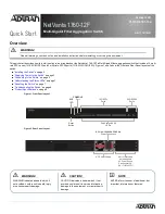
Страница 1: ...e 2 Rear Panel Layout WARNING f Read all warnings cautions notes and installation instructions before installing or servicing this equipment Port Status LAN LEDs 10G SFP Ports 25G SFP28 Ports CONSOLE Port Reset Button SYS LED AC Power Supply Slot for Secondary Hot swappable AC Power Supply Sold Separately PN 17101760PF1 AC Line 100 240V 50 60 Hz Power Connection f WARNING f CAUTION g NOTE WARNING ...

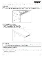
Страница 2: ...is Insert the provided screws and tighten them with a screwdriver to secure the brackets Figure 3 Attaching Brackets to the Switch 2 Position the chassis in the stationary equipment rack Allow 1 inch of clearance between units NOTE g Refer to the national state and local electrical codes for the requirements for power grounding wiring and installation methods CAUTION f CAUTION f The NetVanta 1760 ...

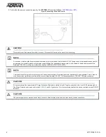
Страница 3: ...t Supplying Power to the Switch To connect the AC power cord to the switch complete the following steps 1 Connect the AC power cord to the AC power receptacle on the rear panel of the switch 2 Connect the other end of the AC power cord to a properly grounded AC power outlet The AC branch circuit socket outlet must be installed near the equipment and must be easily accessible NOTE g Rack mount brac...

Страница 4: ...but it can be ordered directly from ADTRAN P N 17101760PF1 NOTE g The installation of this product must comply with the national state and local electrical code requirements as applicable The AC branch circuit overcurrent protection must be a fuse or circuit breaker rated 125 VAC 20 Amps maximum or 250 VAC 16 Amps maximum CAUTION f CAUTION f It is recommended that an external AC Surge Protection D...

Страница 5: ... via standard Ethernet LAN cable The Ethernet cable will be required to connect the PC to a copper SFP installed on the switch for Web configuration If the switch is connected to a DHCP server skip to Step 3 2 Reconfigure the PC s IP address and subnet mask as below so that it can communicate with the switch For example the method to change the PC s IP address for a PC running Windows 7 8 x 10 is ...

Страница 6: ...me in the login page Select Login to log into the switch Initial Switch Configuration Using CLI The CLI can be accessed using any one of the two console ports USB RJ 45 available on the switch To establish the connection to the console port the following are needed PC with VT100 terminal emulation software Micro USB to USB cable or a DB 9 to RJ45 Serial Cable the cables are provided along with the...

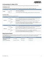
Страница 7: ...The port is transmitting receiving packets and the connection speed is 10 Gbps Amber On The port is enabled and established a link to connected device and the connection speed is 1Gbps 2 5Gbps 5Gbps Flashing The port is transmitting receiving packets and the connection speed is 1Gbps 2 5Gbps 5Gbps Off The port has no active network cable connected or has not established a link to connected device ...

Страница 8: ...is equipment contains no parts that can be serviced by the user Symptoms Possible Causes Suggested Solutions System LED is OFF The switch is not receiving power 1 Check if correct power cord is connected firmly to the switch and to the AC outlet socket 2 Cycle the power on the switch by unplugging and plugging the power cord back into the switch 3 If the LED is still off try plugging the power cor...

Страница 9: ...at that is electrically grounded The following configuration guides provide additional information for this ADTRAN product available online at https supportcommunity adtran com Configuring the CLI in ASE Configuring QoS in ASE Configuring Layer 2 Services in ASE Configuring PoE in ASE Configuring DHCP in ASE Configuring MRP and MVRP in ASE ASE Command Reference Guide For ADTRAN training inquiries ...

Отзывы: