Total Access 3000 23-Inch Chassis Installation and Maintenance Practice
12
61181001L1-5E
DATA CONNECTIONS
Removing Rear Plastic Guards
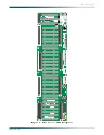
The large rear Plexiglass guard covering the backplane is a safety feature of the Total Access
3000 designed to keep personnel and equipment from contacting potentially high voltage
exposed at some backplane locations. Following the sequence of steps outlined in this practice
will allow the service provider to remove the guards once, make all the necessary Total Access
3000 Chassis backplane connections, and then reinstall the guards. To remove the guards,
perform the following steps:
1. Using a #1 phillips-head screwdriver, remove the long, thin Plexiglass guard covering the
wire-wrap terminals at the bottom of the backplane. It is held in place with two screws.
2. Carefully remove the guard by pulling it straight from the backplane.
3. Using a #1 phillips-head screwdriver, remove the four screws holding the large guard in
place.
4. Carefully remove the large guard by pulling it straight back from the backplane.
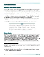
NOTE
Wire tie anchors are pre-installed on the Total Access 3000 Chassis
backplane to secure the 64-pin amphenol connectors. It is easier to
thread the wire ties through the anchors while the backplane
guard is removed. ADTRAN recommends using the wire ties
provided to secure the amphenol connectors. Thread the wire ties
through the anchors at this time, with the guard removed.
Wiring Clocks
The Total Access 3000 Chassis accepts either BITS or composite clock inputs from an external
timing source. When deployed as a DSLAM system, an optional Stratum 3E Clock Module
(P/N 1181930L1) can be used as a timing source that provides a backup clock signal. The
module works in conjunction with the DS3 Cell Switch Module (CSM) to provide holdover
capability upon the loss of the primary timing source, typically an external DS1 BITS clock. As
an Office Repeater Bay deploying HDSL or T1, no clock input is required. As an Office
Repeater Bay deploying ISDN, a composite clock input may be used. Future services may
require these or other clock inputs; the Total Access 3000 Chassis can accommodate them.
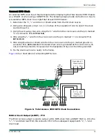
Connect 64 kHz Composite Clock
An external composite clock input may be used when deploying ISDN from Total Access 3000
Chassis. To wire an external composite clock to a single Total Access 3000 Chassis, perform
the following steps:
1. Determine the “
+
”, “
–
” and drain or ground wires from the CO clock source.
2. Using wire strippers, strip 1 to 1-1/2 inches of the insulation from the end of the clock
source twisted pair, shielded, drop wire.

