


Power Connections
61181001L1-5E
11
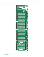
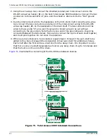
7. Connect three more power wires, connecting the “A” CO –48 VDC return with
TS1 –48 VDC
RET
; “B” CO –48 VDC supply with
TS2 –48 VDC –48 SEC
; and “B” CO –48 VDC return with
TS1 –48 VDC RET
. Secure the wires to the backplane with wire tie through the tie anchor.
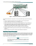
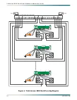
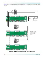
NOTE
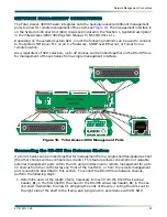
for an example of multiple shelves powered by a single
equipment bay fuse panel.
Apply Power and Check Voltage
Before proceeding further, ensure that power has been correctly applied to the chassis. The
proper voltage to Total Access 3000 Chassis is –48 VDC, with an operating range of –42 VDC
to –56 VDC.
WARNING
Installing fuses in the fuse alarm panel at this stage will provide
power to the chassis. There will be power to pins on the backplane
and inside the chassis. Exercise caution to avoid electric shock.
NOTE
The branch circuit overcurrent protection shall be a fuse or circuit
breaker rated for –48 VDC at 20 amps. Include the appropriate
input current rating for the product.
1. Install the 20 amp fuses in the slots in the fuse and alarm panel that service the Total
Access 3000 Chassis.
2. Using a voltmeter, place the common (normally black) lead on the
TS1 –48 VDC RET
terminal and the DC volts (normally red) lead on the
TS1 –48 VDC –48 PRI
terminal. The
reading should be in the operating range of –42 VDC to –56 VDC, with a nominal value of
–48 VDC. Note the “–” polarity.
3. Using a voltmeter, repeat step
2
, using the
TS2 –48 VDC RET
terminal and the
TS2 –48 VDC
–48 SEC
terminal.
4. Remove the fuses from the fuse and alarm panel slots, securing power to the Total Access
3000 Chassis.