10
Installation
2.2
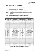
PCI-8154 Outline Drawing
Figure 2-1: PCB Layout of the PCI-8154
X
CN3: Input / Output Signal Connector (100-pin)
X
K1 / K2: Simultaneous Start / Stop Connector
X
CN4: Manual Pulsar
X
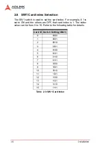
SW1: DIP switch for card index selection (0-15)
X
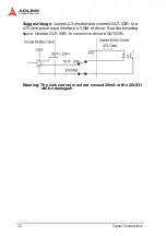
JP2-JP9: Pulse output selection jumper (Line Driver / Open
Collector)
Содержание PCI-8154
Страница 4: ......
Страница 28: ...18 Installation ...
Страница 47: ...Signal Connections 37 and stop signals to STA and STP pins on the K1 connector of the first PCI 8154 card ...
Страница 48: ...38 Signal Connections ...
Страница 98: ...88 Operation Theory ...
Страница 102: ...92 MotionCreatorPro 5 3 2 Select Menu The select menu appears after running MotionCreatorPro It is used to ...
Страница 103: ...MotionCreatorPro 93 5 3 3 Card Information Menu In this menu it shows some Information about this card ...
Страница 104: ...94 MotionCreatorPro 5 3 4 Configuration Menu In the IO_Config_1 menu users can configure ALM INP ERC EL ORG and EZ ...
Страница 106: ...96 MotionCreatorPro In the IO_Config_2 menu users can configure LTC SD PCS and Select_Input ...
Страница 108: ...98 MotionCreatorPro In the Pulse INT_Config menu users can configure pulse input output and move ratio and INT factor ...
Страница 129: ...MotionCreatorPro 119 5 3 8 Help Menu In this menu users can Click Mouse Right Key to show Help Infor mation ...
Страница 130: ...120 MotionCreatorPro ...
Страница 206: ...196 Function Library Pos Latch data Position ...
Страница 224: ...214 Function Library ...
Страница 226: ...214 Connection Example ...


