background image

Technical manual ADITRAT                               


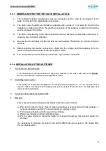
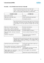
2.3.1.  GENERAL NOTES FOR THE VALVE INSTALLATION: 


1.-  The softener must be installed very close to a draining point in order to discharge in it the 

water coming from the regeneration processes.  


2.-  The drain pipe should be as shortest as possible, with a pass of ½” at least. It should not be 

installed in a higher point than the draining connection of the softener in order not to limit the 

suction process of the brine.  


3.-  The drain outlet leading to the drain should be free fall, without any obstacles interrupting or 

reducing the connection diameter.   


4.-  Be sure that the softener and the salt tank are well levelled. Place them on a clean and plate 

surface.  


5.-  Before realizing the electric connections, check that the voltage and the frequency from the 

mains correspond to the ones of the valve (220V, 50Hz). 


6.-  The valve power point should be provided with a good earth connection.  


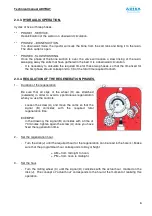
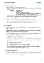
2.3.2. INSTALLATION OF THE SOFTENER 


1.-  Connection of the drain pipe. 


-  The  connection  must  be  realized  in  the  point  marked  in  the  valve  with  the  word  DRAIN, 

which is situated on a side of the programmer head. 


2.-  Assembly brine injector. 


-  This series of valves are equipped in our factory with the injector nr. 3. The function of the 

injector  disk  is  to  create  the  necessary  vacuum  to  extract  the  brine from  the  salt tank  and 

inject it into the softener.  


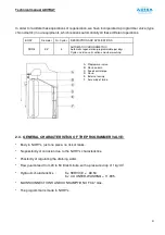
3.-  Correspondence pressure-injector disk. 


4.-  Salt tank. 


-  This is the procedure to measure the height of the brine valve floater:  


a)  Pour into the tank as many litres of water as the litres of resin contained in the softener. It 

is recommended to add a 20% more of water as a safety margin.  

b)  Fill the tank with salt up to the level of the chimney.  

c)  Wait a few minutes until the salt settles down.  

d)  Put  the  valve  floater  at  the  same  height  as  the  level  the  water  has  reached  inside  the 

chimney.  


-  It is necessary to maintain the level of the salt ALWAYS above the level of the floater after 

the first regeneration.  


Содержание ADITRAT

Страница 1: ...ADITRAT REFILLING WATERS TREATMENT TECHNICAL MANUAL OF INSTALLATION USE AND MAINTENANCE 3 2011bis ...

Страница 2: ...njector 7 2 4 Maintenance guide 8 3 DISPENSER 11 3 1 Working conditions 11 3 2 Start up 11 3 3 How to regulate the dosage 11 3 4 Maintenance 11 3 5 Recommendations 12 4 DESCALING PRODUCT 12 4 1 Characteristics 12 4 2 Chemical properties 12 4 3 Treatment doses 12 Data indicated in the present manual are liable to changes ADISA CALEFACCIÓN ARTICULOS DOMESTICO INDUSTRIALES CALEFACCIÓN S L has the rig...

Страница 3: ...nd sludge will start to settle down in the installation preventing the equipments to correctly operate the radiators to work at 100 of their capacity and the same will happen to the heating and cooling generators This process will cause deterioration of the installation and of the equipments installed So it would be important to avoid realizing refillings with non treated water and if this is not ...

Страница 4: ... 2 SOFTENER 3 DISPENSER 4 TANK FOR QUICK REFILLING 5 WATER METER 6 NON RETURN VALVE 7 CUT OFF VALVES E COLD WATER INLET C CONNECTION TO THE INSTALLATION L QUICK REFILLING OF THE PRODUCT V DRAINING DIMENSIONS OF THE BASE 800 x 680 mm HEIGHT 1050 mm 2 E 1 C 6 5 3 L ...

Страница 5: ...would work with soft waters Furthermore this can cause overheating of the materials with the consequent break of the equipments All these problems disappear with the use of soft or decalcified water THE SOFTENER There are various effective methods to reduce the water hardness the most appropriate are deionization distillation reverse osmosis and the ionic interchange decalcification The softener i...

Страница 6: ...rvice salt suction and slow washing A Programmer valve B Resin column C Feed central pipe D Resin E External casing F Assembly of brine 2 3 GENERAL CHARACTERISTICS OF THE PROGRAMMER VALVE Body in NORYL just one piece no risk of leaks No possibility of corrosion due to the NORYL characteristics Possibility of regulating the draining water Flow guaranteed from 20 to 50 litres minute with a pressure ...

Страница 7: ... a good earth connection 2 3 2 INSTALLATION OF THE SOFTENER 1 Connection of the drain pipe The connection must be realized in the point marked in the valve with the word DRAIN which is situated on a side of the programmer head 2 Assembly brine injector This series of valves are equipped in our factory with the injector nr 3 The function of the injector disk is to create the necessary vacuum to ext...

Страница 8: ...GULATION OF THE REGENERATION PHASES 1 Duration of the regeneration Be sure that all clips of the wheel H are stretched outwards in order to avoid a spontaneous regeneration when you use the controls Loosen the screw A and move the cams so that the signal B coincides with the required total regeneration time EXEMPLE In the drawing the signal B coincides with a time of 70 minutes tighten again the s...

Страница 9: ...r must be between 2 kg cm2 and 4 kg cm2 Check it A pressure lower than 2 kg cm2 does not allow obtaining correct brine suction and an excessive pressure risks to damage the valve or the salt suction system In case the pressure from the mains is higher than the maximum pressure recommended it is important to install a reducing pressure valve before the softener Check the prefixed times in the progr...

Страница 10: ...neration Not sufficient brine quantity Raise the position of the floater in the brine valve Excessively fast brine suction Change the injector disk for one of greater number Check the height of the floater Low concentration of brine due to a reduction of the diameter or to a constriction in the suction pipe Eliminate the constriction Change the suction pipe Low concentration of brine due to dirtin...

Страница 11: ... or change it Injector s filter is obstructed full of dirtiness Eliminate dirtiness or change it Obstructed injector Grooves covered with dirtiness Clean the injector disk grooves Change Insufficient inlet pressure Watch that the minimum pressure is higher than 2 kg cm2 Disconnect the brine suction pipe from the floater valve During the induction cycle no suction is detected on the contrary water ...

Страница 12: ...h time for sucking brine Change the injector for another one of greater size Suction of excessive quantity of brine Check the floater height in the salt valve Lower it PROBLEM WATER KEEPS ON COMING OUT FROM THE DRAIN AFTER THE REGENERATION HAS ENDED Damaged drain valve It does not adjust correctly or lack of a O ring gasket Change the valve Clean the drain valve Put a O ring gasket Programme cams ...

Страница 13: ...e dispenser s body P004 Pull down the spring Take out the pin and place it where you prefer Dosage Not use 0 5 0 8 1 Release the spring so that it can go back to its initial position Screw the dispenser s body P004 3 4 MAINTENANCE Respect the flow and pressure values indicated in paragraph 4 Use the dispenser with cold or tepid water and if the products to be dispensed are solid take care that the...

Страница 14: ... liquid Smell slightly ammoniac Density 1 2 gr c c ph pure product 10 7 ph in dissolution at 1 9 5 It is compatible with glycolic antifreeze 4 2 CHEMICAL PROPERTIES This product should be employed in closed circuits cold or hot water or in those cases requiring the maximum effectiveness that no other products can achieve Thanks to its chemical stability and its dispersing action it has an excellen...

Страница 15: ...13 ...

Отзывы: