background image

Operation and Maintenance

19

LED Label

(Right Indicator Panel)

Color

State

Operating Condition

Write Protected

Orange

ON

OFF

Tape is write-protected.

Tape is write-enabled.

Tape in Use

Yellow

Blinking

ON

Tape is moving.

Tape is loaded; ready for use.

Use Cleaning Tape

Yellow

ON

Remains on after
unloading cleaning
tape

After cleaning,
turns on again
when reloading
data cartridge

Drive head needs cleaning, or the tape is bad.

Cleaning attempted, but tape expired, so cleaning
not performed.

Problem data cartridge. Try another cartridge.

Operate Handle

Green

ON

OFF

OK to operate the Cartridge Insert/Release Handle.

Do not operate the Cartridge Insert/Release Handle.

All Right Indicator
Panel LEDs,
or,
All Left Indicator
Panel LEDs

ON

Blinking

POST is starting.
An error has occurred.

(continued on next page)

Содержание Tape Array 5

Страница 1: ...Installation and O perating Guide Tape Array 5 Rackmount Enclosure...

Страница 2: ...ther based on warranty contract or other legal theory Printed in the U S A August 1999 Document Number 62 0115 01 Rev D Corporate Headquarters Advanced Digital Information Corporation Shipping Address...

Страница 3: ...ch patents are pending or have been granted By publishing this information ADIC Europe conveys no license under any patent or any other right ADIC Europe makes no representation or warranty with respe...

Страница 4: ...a circuit different from that to which the receiver is connected Consult the dealer or an experienced radio TV technician for help You may find the following booklet prepared by the Federal Communica...

Страница 5: ...e Vigny 78112 Fourqueux France USA Type of equipment External Digital Linear Tape Drive Enclosure Model No T5 Year of Manufacture 1998 conforms to the following international specifications as require...

Страница 6: ...ll operating and use instructions should be followed 3 Ventilation The product should be situated so that its location or position does not interfere with proper ventilation 4 Heat The product should...

Страница 7: ...peratures Keep the unit away from direct sunlight strong magnetic fields excessive dust humidity and electronic electrical equipment which generate electrical noise Hold the AC power plug by the head...

Страница 8: ...viii Blank Page...

Страница 9: ...rs 9 SCSI Cables and Jumpers 9 SCSI Terminators 10 SCSI ID Selection Switches 10 Installing in the Rack 11 Chapter 3 Operation and Maintenance 13 Powering on the System 16 Normal Operations 16 General...

Страница 10: ...x Table of Contents Blank Page...

Страница 11: ...1 Chapter 1 Introduction This Chapter p provides a physical description of the switches indicators and connectors on the rear panel of the T5 Enclosure...

Страница 12: ...5 chassis and are retained with captive screws The carriers contain SCSI and power connectors which dock with mating connectors mounted inside the T5 chassis and provide all power and data connections...

Страница 13: ...hich are used to connect the T5 Enclosure to the host computer SCSI bus ses or to other devices on the SCSI channel Ten HD68 connectors allow a separate SCSI bus connection to each drive installed in...

Страница 14: ...tary power control and sharing modules Each supply plugs into the rear of the T5 and can be removed or replaced while the other supply keeps the system fully operational There is a normally green indi...

Страница 15: ...ned in the power supply modules and whose status is reflected by the power supply status indicators The other two fans are mounted on the chassis rear panel and are easily removed and replaced while t...

Страница 16: ...6 Introduction Blank Page...

Страница 17: ...7 Chapter 2 Installation This Chapter p explains the steps necessary to install your T5 enclosure...

Страница 18: ...semblies and internal SCSI data cables as ordered Accessories box containing this Installation and Operating Guide a right and a left side rack mount support bracket and an accessory bag containing an...

Страница 19: ...the SCSI host they are connected to Termination can be active or passive ADIC recommends using active termination on a single ended bus All termination must be external Never use internal terminators...

Страница 20: ...ical device on a SCSI bus SCSI ID Selection Switches The SCSI ID selection switches are located at the top near the center of the T5 rear panel Each switch has sixteen positions 0 through 15 and the s...

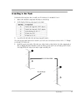
Страница 21: ...ps 10 32 x 12 Washer flat 10 12 Washer lock 10 3 Locate the left and right side rack mount support brackets The rack mount support brackets are secured to your racks rear vertical rails with four 10 3...

Страница 22: ...pping them into the holes in each rail The cage nuts should be at the same vertical height as those securing the support brackets 7 Remove the front bezel from the T5 Enclosure It is held in place by...

Страница 23: ...ure to your racks front vertical rails using a 10 32 x Phillips screw through each cage nut as shown below 10 Secure the bezel to the T5 Enclosure by placing it over the ball studs and pushing firmly...

Страница 24: ...14 Installation Blank Page...

Страница 25: ...15 Chapter 3 Operation and Maintenance This Chapter p explains how to operate the T5 Enclosure...

Страница 26: ...5 Enclosure and your choice of application software are installed and configured you can automatically perform backup and restore operations via the application software You do not need to intervene u...

Страница 27: ...For example if the actual tape density is 2 6 then the LED turns ON next to the 2 6 label When the Density Override LED blinks you can select a density The drive is ready for use 3 A cartridge is pre...

Страница 28: ...on and Maintenance Drive Operating Conditions Use the following illustrations and tables to determine each drive s operating condition Figure 3 1 DLT 7000 Drive Front Panel Figure 3 2 DLT 7000 Drive F...

Страница 29: ...ng cleaning tape After cleaning turns on again when reloading data cartridge Drive head needs cleaning or the tape is bad Cleaning attempted but tape expired so cleaning not performed Problem data car...

Страница 30: ...from BOT 20 0 DLT4000 DLT7000 DLT8000 Yellow ON default Blinking Tape is recorded in 20 0 format Tape is recorded in another density You selected this density for a write from BOT 35 0 DLT7000 DLT800...

Страница 31: ...ridge if you move the Write Protect switch to the right the tape is write enabled and data can be written to or erased from the tape if it is not software write protected After loading the data cartri...

Страница 32: ...the way to the right Caution A data cartridge can only be loaded when the Operate Handle LED is ON Do not attempt to open the Cartridge Insert Release Handle unless this LED is ON steady 2 Lift up on...

Страница 33: ...s Tape is unloaded into the cartridge and the cartridge can now be removed or if the drive is unloaded a cartridge can now be inserted All LEDs Blinking An error has occurred during operation Removing...

Страница 34: ...irst step if the Use Cleaning Tape LED is illuminated on the drive Note The cleaning cartridge is exhausted after it has performed 20 cleanings The cleaning tape includes a label with 20 small boxes p...

Страница 35: ...idge 3 Use Cleaning Tape LED still illuminates after you clean the drive head Your data cartridge may be causing the problem Try another data cartridge 4 Use Cleaning Tape LED illuminates after you lo...

Страница 36: ...ime between failure MTBF rating The power supplies are located at the rear of the T5 chassis If either supply needs replacement the entire power supply assembly should be unplugged and replaced Power...

Страница 37: ...ocation of these screws Figure 3 3 Power Supplies 2 Use the handle on the module to pull the supply assembly from the chassis The module docking connector will disengage from the chassis connector 3 R...

Страница 38: ...two screws at the top of the fan as shown in Figure 3 2 Figure 3 4 Fan Removal 2 Gently pull the fan away from its mounting location Reach inside the T5 chassis and disconnect the red DC power connec...

Страница 39: ...Power Removal 3 Replace the fan as soon as possible making sure that the power connector on the fan is firmly mated with the DC power connector in the T5 chassis 4 Reinstall the two screws to secure...

Страница 40: ...30 Operation and Maintenance Blank Page...

Страница 41: ...31 Chapter 4 Troubleshooting and Diagnostics This Chapter p describes the effects of high humidity on the T5 Enclosure p explains what to do when you need technical support...

Страница 42: ...he temperature is changing by more than 10 C per hour When You Need Assistance When Calling the ADIC Technical Assistance Center Customer Support is provided free of charge to all ADIC customers durin...

Страница 43: ...warranty card to ADIC Call the ADIC Sales Department at 425 881 8004 for details Warranty exchange service is provided at no charge to customers with validated warranties If the item is NOT in warrant...

Страница 44: ...34 Troubleshooting and Diagnostics Blank Page...

Страница 45: ...35 Appendix A Specifications This Appendix p contains specification information on the T5...

Страница 46: ...fans Electrical Interface SE or HVD Fast Wide SCSI DLT7000 SE LVD or HVD Fast Wide SCSI DLT8000 Physical Interface 68 contact shielded high density device connector Reliability Maintenance Use cleanin...

Отзывы: