

www.adeept.com
65
Short-press
: Press the button and release it quickly. At this time, the LED will turn red when
pressed. When it is released, it will change back to the previous color.
Long-press I
: Press and hold the button for a while and then release. Specifically, the moment the
button is pressed, the button turns red. After a short period of time, the LED turns blue and dims
gradually. Release the button when the blue becomes completely dark out.
Long-press II
: Press and hold the button until the LED turns red - turns blue - blue dims gradually-
becomes bright light blue and then release.
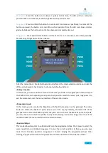
After the normal boot, the default operation interface is the mode selection interface. Under the
offline state, RaspArm has 4 modes to choose by default, which are:
<Rotary Encoder>
In this mode, you can control the servo with the rotary encoder on the gamepad. Rotate to adjust
the PWM of the corresponding servo port; short-press to switch the servo port; long-press II to
exit the mode and enter the menu interface of the selection mode.
<Movement Input>
In this mode, you can control the RaspArm with the attitude sensor on the gamepad. The rotary
knob can control the PWM of port3 (the servo of the clip by default); the lateral tilt of the
gamepad can control the PWM of port0; the pitch tilt can control the PWM of port1 and port2;
you can choose to control the specific one by short-pressing the button; long-press II to exit the
mode and enter the menu interface of the selection mode.
<Keys and Setps>
This mode allows RaspArm to automatically loop the programmed steps. Short-press to select the
servo needs to be controlled; Long-press I to save the current position; In theory, you can save
more than 20 million positions. Long-press II to start looping the programmed steps. After
starting, long-press II to exit the loop and enter the menu interface of the selection mode.
Содержание RaspArm
Страница 1: ...www adeept com 1...
Страница 14: ...www adeept com 11 If a warning window prompts click Yes...
Страница 25: ...www adeept com 22 2 Connect the battery holder and Raspberry Pi Note that the switch is OFF...
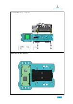
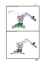
Страница 38: ...www adeept com 35 Assemble the following components Effect diagram after assembling M3 25 Screw X3 M3 Nut X3...
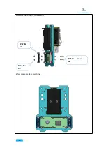
Страница 40: ...www adeept com 37 Assemble the following components Effect diagram after assembling M3 25 Screw X2 M3 Nut X2...
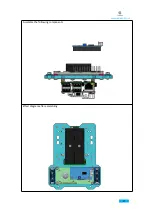
Страница 49: ...www adeept com 46 Assemble the following components Effect diagram after assembling M3 35 Screw X6 M3 Nut X6...
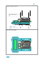
Страница 51: ...www adeept com 48 Assemble the following components Effect diagram after assembling M3 Nut X4 M3 16 Screw X4...
Страница 55: ...www adeept com 52 Assemble the following components Effect diagram after assembling M3 8 Screw X4...
Страница 58: ...www adeept com 55 Assemble the following components Effect diagram after assembling M2 5 8 Screw X4...
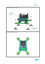
Страница 60: ...www adeept com 57 Assemble the following components Effect diagram after assembling...
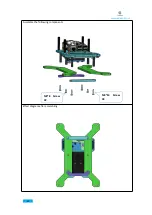
Страница 64: ...www adeept com 61 Assemble the following components Effect diagram after assembling Cap Nut X4 Sucking Disc X4...
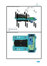
Страница 66: ...www adeept com 63 Assemble the following components Effect diagram after assembling M3 8 Screw X4...
Страница 70: ...www adeept com 67...