23
INST
ALLA
TION
CONFIGURA
TION
OPERA
TION
FUR
THER
INFORMA
TION
INDEX
APPENDIX A - Cables for use with digital extenders
Introduction
The demands of extending high resolution DVI and HDMI digital video signals are
considerable and mean that it is not possible to use Cat5e cabling to achieve the
maximum extension distance of 50 meters. The large video bandwidth involved means
that to achieve the best possible performance from digital extenders, it is vital that the
correct cabling is chosen.
There are three important factors to consider when choosing a cable for use with digital
extenders.
IMPORTANT: Please remember that even though they use network-style
cables, the link ports of the modules are NOT Ethernet ports and must not
be connected to network switches or any other devices.
Types of cable
Twisted pair cables can have either solid or stranded conductors. Solid cables come
in bulk spools and are often referred to as infrastructure or bulk cabling. They are less
flexible than stranded cables but have less attenuation. These cables are typically run
throughout a building and terminate at the rear of a wall plate.
Types of RJ45 connector
For each type of cable there is also an associated RJ45 connector. It is important that the
correct type of connector is used for the type of cabling.
Insulation displacement
RJ45 connectors are designed to work with solid conductor cables
while
insulation piercing
RJ45 connectors are designed to work with stranded conductor
cables.
Stranded cabling is found in patch cables and is intended to connect the front of the wall
plate to the extender or computer using RJ45 connectors. They need to be more flexible
because the cabling gets disconnected and connected constantly.
For a digital extender application, solid conductor cables give a better performance as
these allow for a higher bandwidth and have less attenuation. Ideally a thickness of 22
AWG should be used.
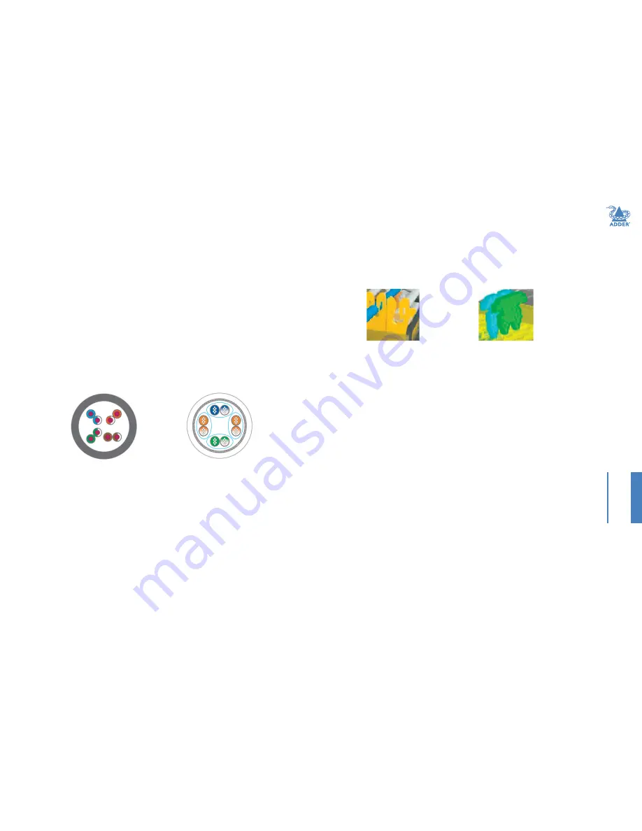
Solid
Stranded
The teeth of the insulation displacement connectors are designed to straddle and hug
the sides of the solid center conductor of the cable.
The teeth of the insulation piercing connectors penetrate the middle of the cable and
nest in between the stranded wires. If insulation piercing connectors are used on solid
core cable then the connection will not be stable as the teeth will try to but are unable
to penetrate the solid center conductor. The teeth will then slide off the solid core and
not make a stable contact.
Types of shielding
The third and final factor in determining the cable to be used in digital extension is
shielding. The shielding protects the cable from two types of interference, internal
crosstalk and external interference.
Internal crosstalk
is the interference between the
different pairs inside the cable.
External interference
is any interference that comes from
outside the cable. This is caused by many things; proximity to mobile phones, bundling
cables together or running them over lighting fixtures.
Internal crosstalk is most detrimental to digital extension as the signals cannot be
recovered after experiencing crosstalk. You are left with a black screen.
The most common type of shielding is
Screened/Unshielded Twisted Pair
(S/UTP). This has
an overall shield and will protect the signal from external interference. However it does
not provide any protection from crosstalk.
The next type of shielding is
Shielded Twisted Pair
(STP). This has four individual shields,
one for each data pair. This is good for protecting the signal from internal crosstalk but
does not provide an overall shield to protect against external interference.
If you combine the two types of shielding together you have
Screened/Shielded Twisted Pair
(S/STP). This is also sometimes referred to as
Shielded/Foil Twisted Pair
(S/FTP). This has four
individual shields, one for each pair and an overall shield. S/STP is the best cable to protect
against any interference and is the cable choice to be used for digital KVM extension.
Insulation displacement
Insulation piercing


