7351 Series Digital Multimeter Operation Manual
8. MAINTENANCE
8-1
8.
MAINTENANCE
This chapter describes the following information which relates to the maintenance of this instrument.
8.4 Replacing Parts with Limited Life
8.5 Product Disposal and Recycle
8.8 Notes Regarding Repair, Replacement, and Periodic Calibration
8.1
Replacing Fuses
This instrument includes a power fuse and protection fuse. Replace them according to the following proce-
dure.
CAUTION:
1.
To prevent fire and electrical shock, replace with a fuse listed in Table 3-1. Never use an incompatible fuse and
short-circuit the fuse holder.
2.
Whether a fuse has blown cannot be checked by observation. Measure the resistance of the fuse and judge
whether the fuse has blown. (If the resistance is 15
or less, the fuse has not blown.)
3.
Do not cut any of the internal ground wiring in this instrument or disconnect this instrument from ground. This
instrument may become unsafe to operate.
8.1.1
Replacing a Power Fuse
The power fuse is placed in the AC power supply connector on the rear panel.
For more information on how to check and replace the power fuse, refer to Section 3.4.2, “Changing the
Power Supply Voltage.”
8.1.2
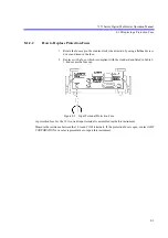
Replacing a Protection Fuse
To prevent fire and injuries when an over-current is supplied to the mA current input terminal, a fast-blow
fuse is included on the rear panel of this instrument.


