
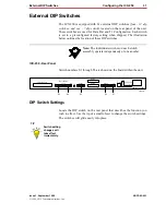
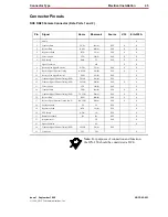
External DIP Switches
Configuring the ICX-250 33
Issue 1, September 1998
ADCP-62-023
© 1998, ADC Telecommunications, Inc.
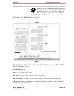
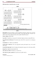
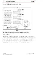
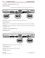
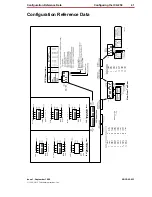
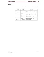
T1 Interface - T1 Clock
(DIP switch - back)
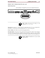
ICX-250 - Rear Panel
Switch numbers S1 through S5 are shown on the board within the unit.
Description: S1 position 4 is used to select the T1 clock source.
Factory Setting: LINE
Line: Clock for the T1 interface will be recovered from the line (receive signal).
Internal: Clock for the T1 interface will be taken from an on-board 1.544 MHz clock meeting the
Stratum 4 requirements.
Note
:
Failure of external clock causes unit to switch
to internal clock. When external clock is restored, the
unit will switch back to external clock source.
120 VAC–.6A 60Hz
24/48 VDC
+ – G
T1
Rx
Tx
T1 Line
T1
Data 2
Data 2
Data 1
1
12 13
24
ON
DIP
1 2 3 4 5 6 7
Alm.
Data 1
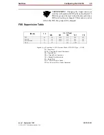
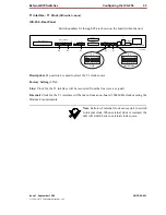
FXS Loopback
FXS Loop Pairs
S5
S4
S3
S2
S1
11268-A
T1
LINE
ON
DIP
1 2 3 4 5 6 7
T1
INTERNAL


