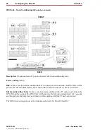
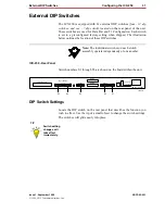
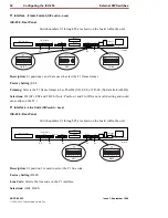
External DIP Switches
Configuring the ICX-250 35
Issue 1, September 1998
ADCP-62-023
© 1998, ADC Telecommunications, Inc.
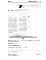
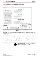
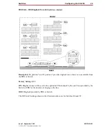
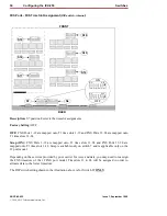
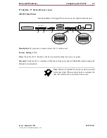
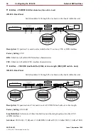
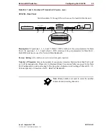
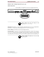
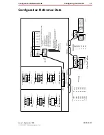
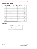
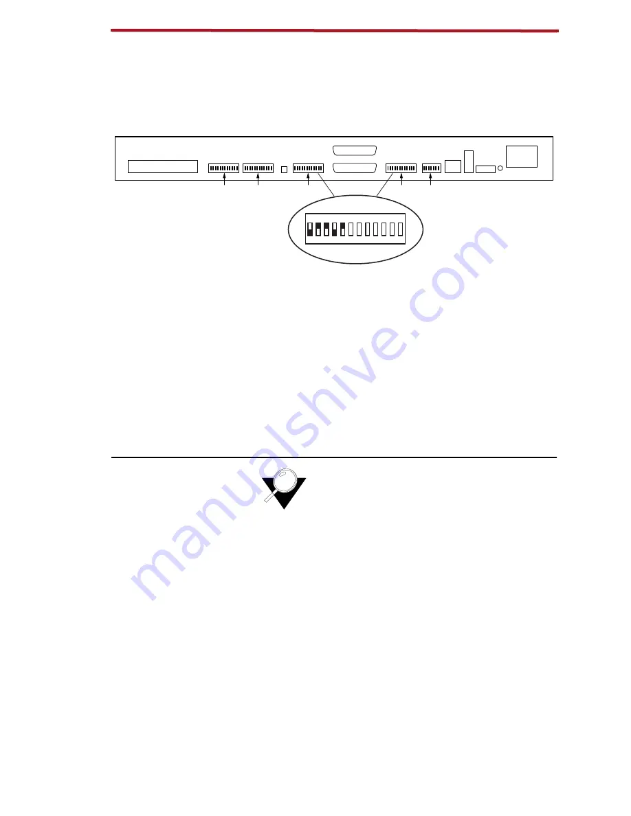
Data Port 1 and 2 - Number of Timeslots
(DIP switch - back)
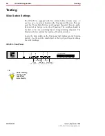
IICX-250 - Rear Panel
Switch numbers S1 through S5 are shown on the board within the unit.
Description: S2 positions 1, 2, 3, 4 and 5 (Data 2 - DIP switch) sets the port parameters for Data
Port 2. S3 positions 1, 2, 3, 4 and 5 (Data 1 -DIP switch) sets the port parameters for Data Port 1.
Both DIP switches are used for Network Data Bandwidth.
Factory Setting: All switches are set to zero (data ports inactive).
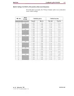
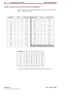
Number of Timeslots: Selects the number of consecutive timeslots that data from Data Port 1 and/
or 2 will be mapped onto. Please refer to Decimal/Binary Conversion Table (see page 36) for Data
Port Configuration to aid in selecting N. Drawing above indicates switch settings if timeslot N = 13.
Selected quantity of timeslots x 64K = Data Port Bandwidth.
Note
:
Binary numbers are used to select the number
of timeslots and starting timeslots.
120 VAC–.6A 60Hz
24/48 VDC
+ – G
T1
Rx
Tx
T1 Line
T1
Data 2
Data 2
Data 1
1
12 13
24
ON
DIP
1
0
1
2 3 4 5 6 7 8 9 10 11 12
Alm.
Data 1
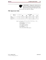
FXS Loopback
FXS Loop Pairs
S5
S4
S3
S2
S1
11271-A
Data 1 / Data 2


