


44 Electrical Installation
Connector Type
ADCP-62-023
Issue 1, September 1998
© 1998, ADC Telecommunications, Inc.
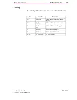
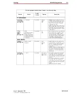
Connector Type
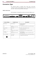
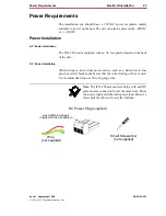
The ICX-250 product is equipped with several types of electrical
connections to the network and power sources. The table below lists each
one of the connectors along with their functionality.
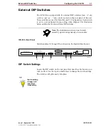
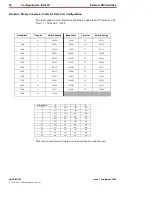
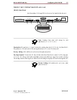
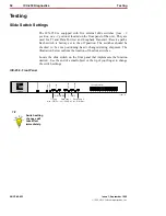
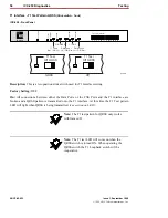
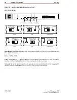
ICX-250 - Rear Panel
Switch numbers S1 through S5 are shown on the board within the unit.
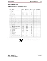
Connector Name
Connector Type
Description
FXS Loop Pairs
25 Pair Amphenol
24 FXS Tip and Ring pair
Signals: TIPn, RINGn
switch for FXS.
Alm.
2 position
(plug included with Kit of Parts)
A relay closure that sends alarms out to an external alarm system.
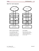
Data 1 and Data 2
DB25 Female
Data Port 1 signals and Data Port 2 signals.
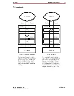
T1 Line
RJ48
Transmit and Receive pairs.
T1
Dual Bantam Jack (monitor jacks)
For bridged access onto the T1 transmit and receive pairs.
24/48VDC (+– G)
1.8 / .9A Max.
3 position
(plug included with Kit of Parts)
For DC power input.
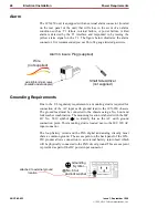
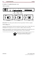
Note: FXSGND must be connected to earth ground regardless of
powering method used.
120 VAC -.6A 60Hz
AC Receptacle
Power input when external 120 VAC 60Hz is used to power the unit.
Earth Ground
Permanent Earth Ground Connection.
120 VAC–.6A 60Hz
24/48 VDC
+ – G
T1
Rx
Tx
T1 Line
T1
Data 2
Data 2
Data 1
1
12 13
24 Alm.
Data 1
FXS Loopback
FXS Loop Pairs
11264-A


